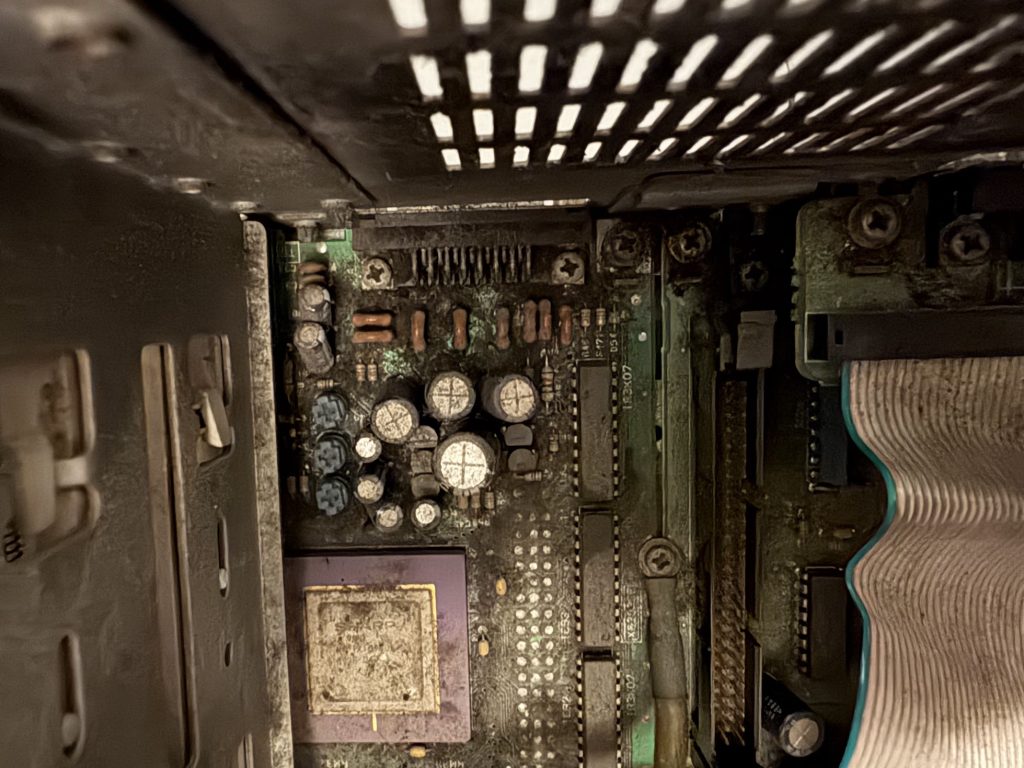
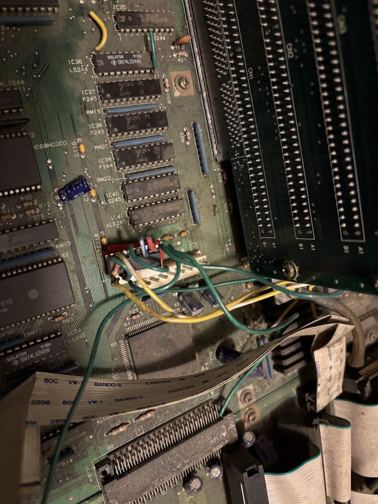
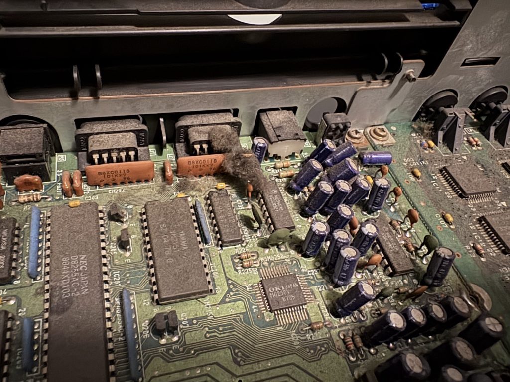
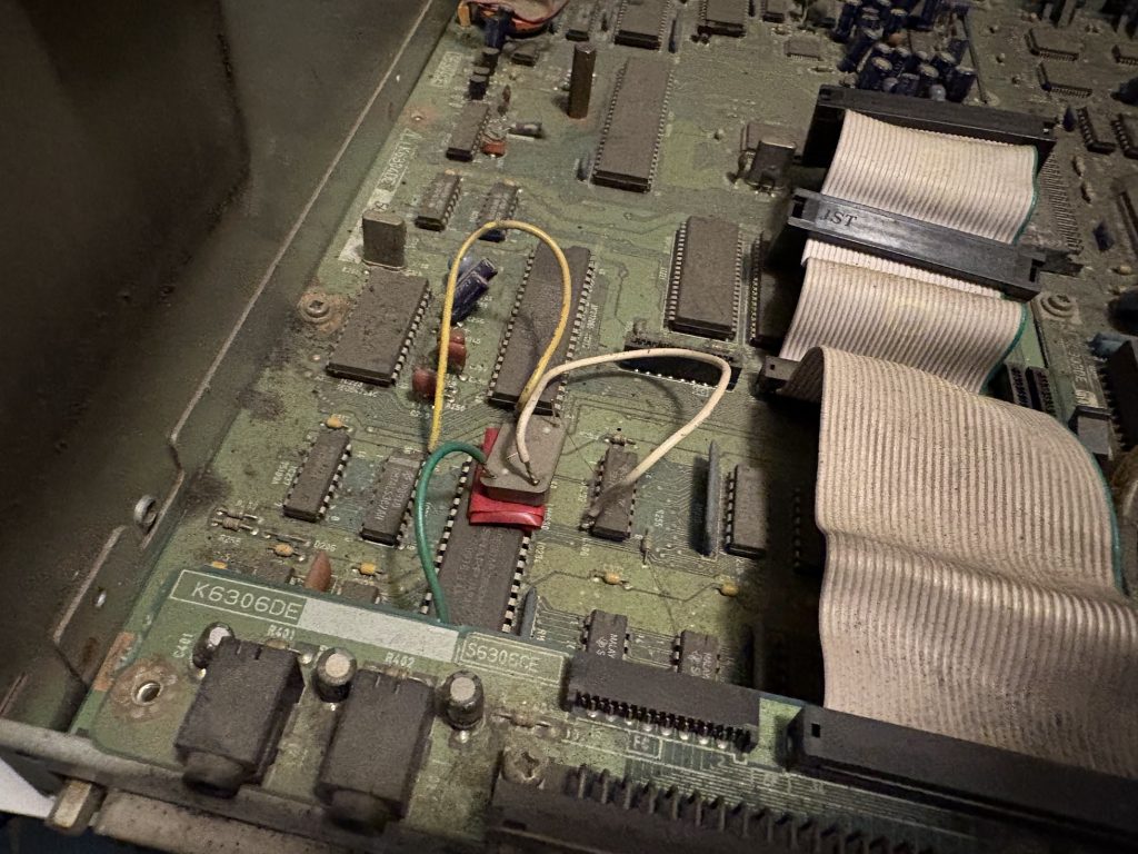
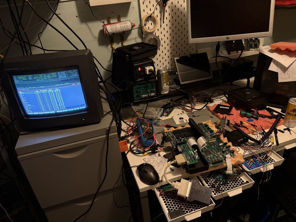
Was expecting it to be non-functional and broken, and it was. It was also impressively filthy. Check this out:
Before
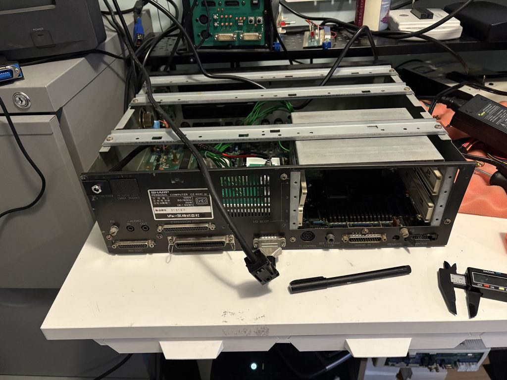
Outsides and insides were… very dirty. There were remnants of an old overclock mod which was partly disconnected.
Floppy drives were not present. Neither was the power supply.
What was however present was this sick as fuck homemade RAM card. Look at this thing. Home etched!
Cleanup and recap
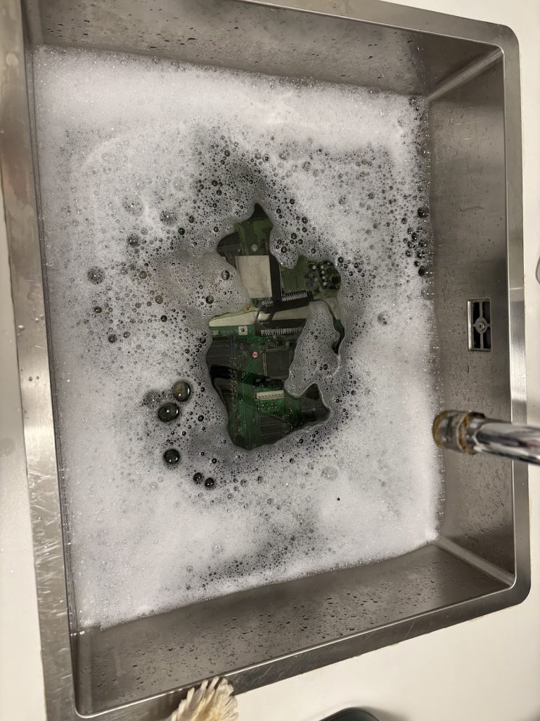
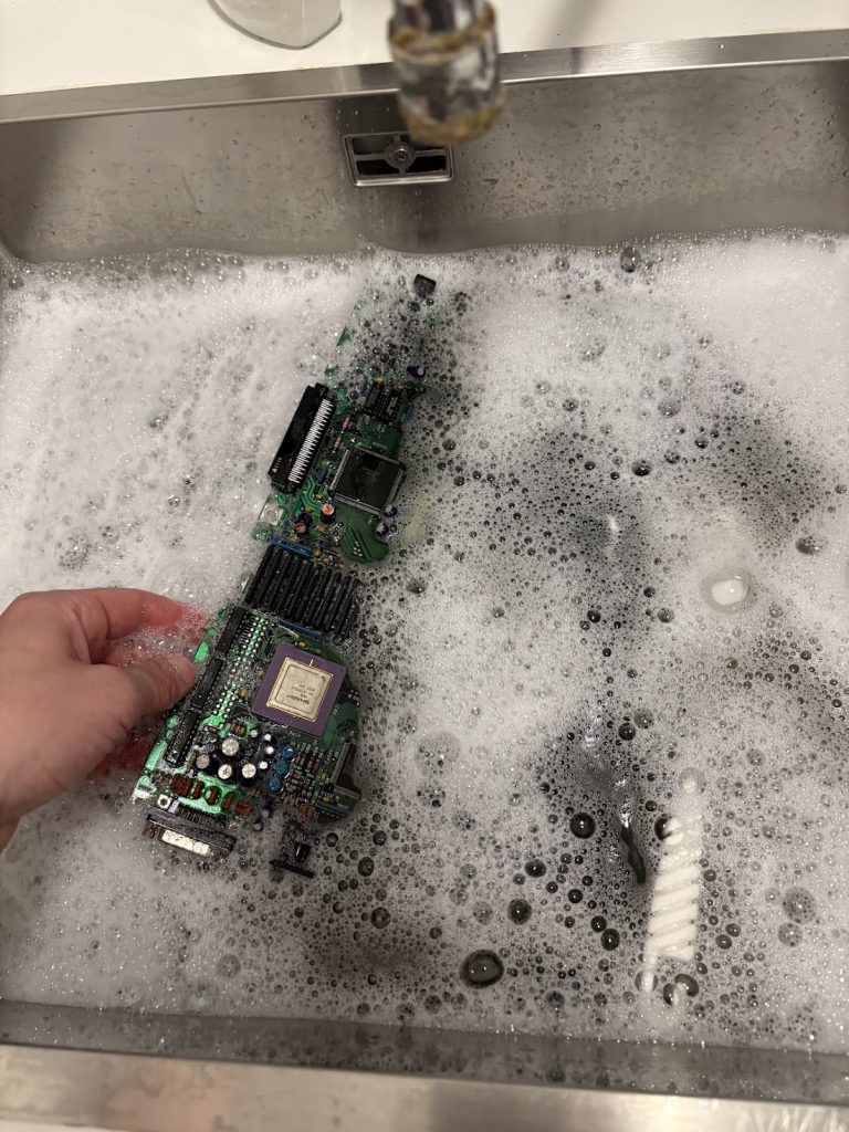
Before I could really do anything with this thing, I had to clean out all the dirt, so it was bath time.
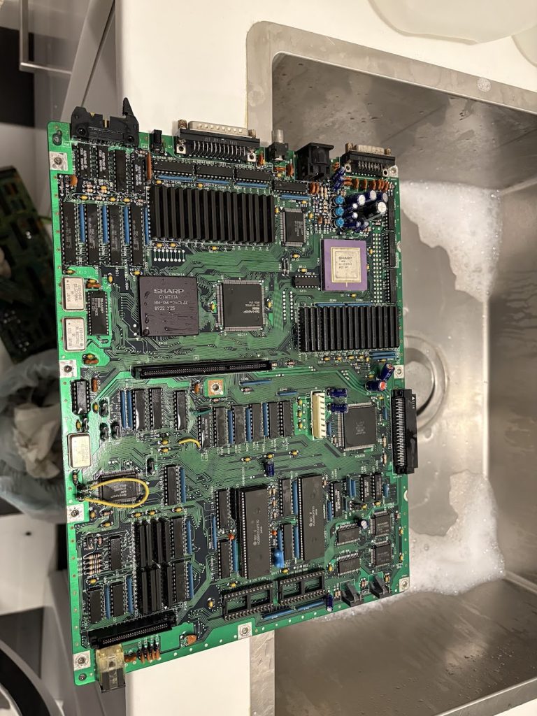
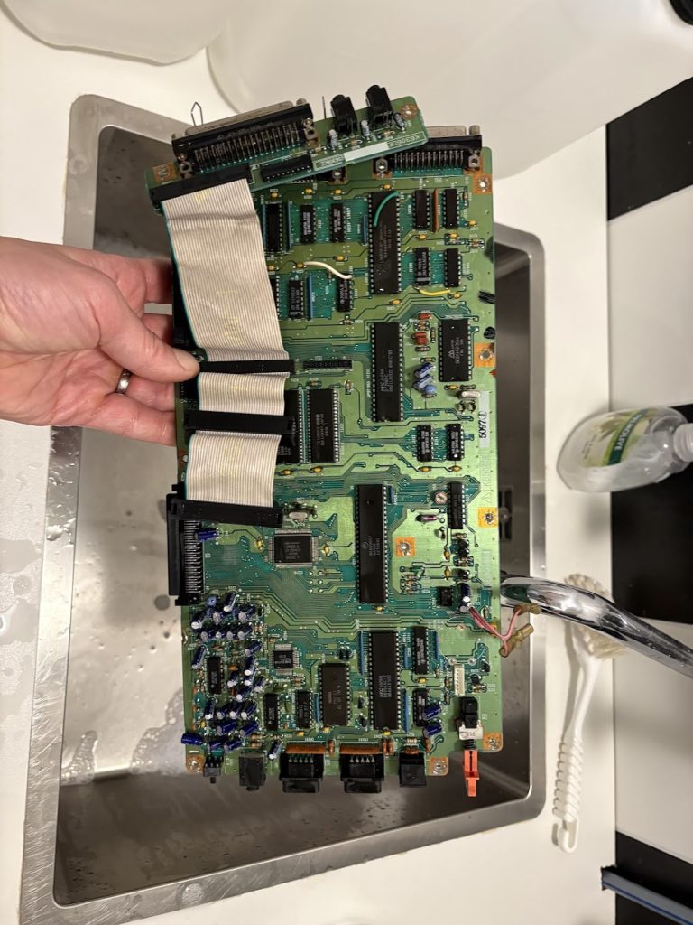
Things cleaned up nicely!
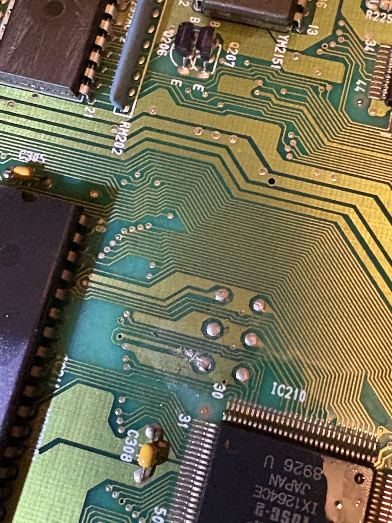
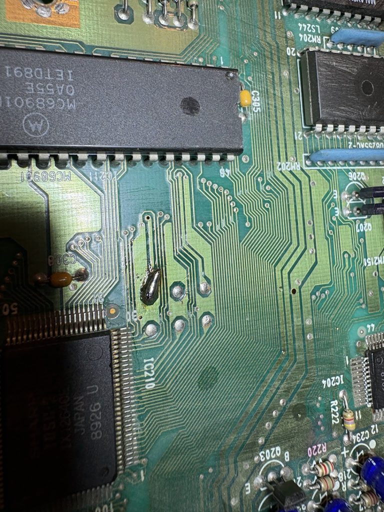
As mentioned, there were some partial overclock mods that had to be removed. In practice this meant rewiring a lifted pin from the CPU clock, and bridging a cut trace which was related to the second oscillator for the IO board.
I tried booting things at this point, but things were very dead, so I just skipped right ahead to doing the recap and battery swap here as well to exclude simple issues.
Booting and PSU
With the regular IPL, the system would not boot at this point due to the missing floppies, but with a custom IPL installed, the system would now boot fine from SASI. Very nice!
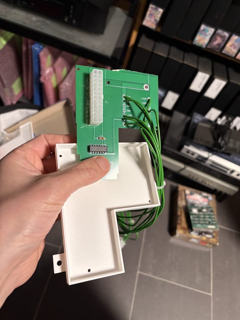
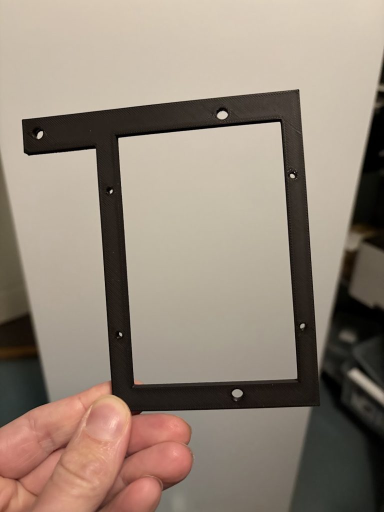
For the missing PSU, I scavenged some old replacement boards I had around, cut them a bit smaller and made a plastic bracked for mounting a Pico-ATX in the case. Turned out OK.
I decided to not have an internal DC converter, and instead running the device off 12V DC, so I 3d printed a small holder for the connector which turned out well.
Extras
Since the device only came with 1MB RAM, I added an internal 1MB expansion as well as a 8MB Polykubos RAM+Midi card.
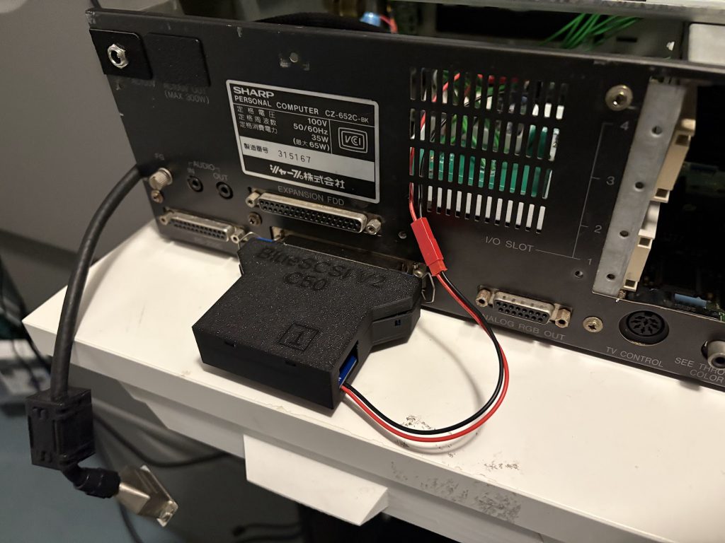
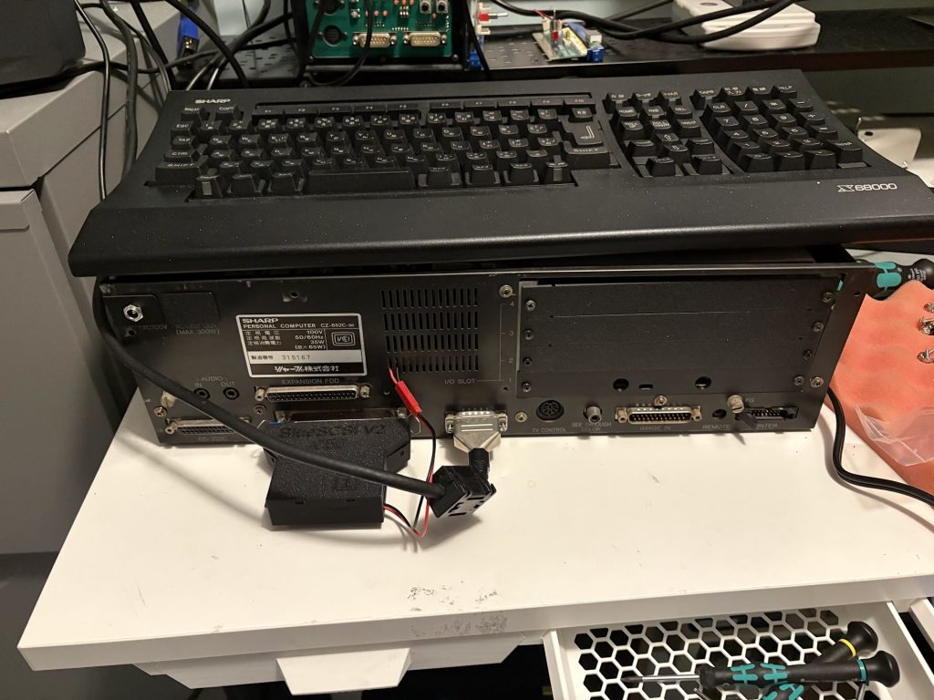
For Booting the system, I use a Bluescsi V2 Centronics version. The X68000 Pro does not provide termination power over the SASI port, so I went with a slightly hacky fix of just adding a 5V connector through a hole in the back of the case.
Case cleanup
Stickers were removed by a combination of violence, IPA and scrubbing with a soft brush. Case was washed off thoroughly. IO covers were 3d printed. There’s a few deep scratches but other than that, things look pretty good now!
Final thoughts
There were no real setbacks in this restoration, unlike the Compact I worked on previously.
While there were still a lot of steps to perform to get everything up and running, it was mostly smooth sailing, and I could chip away at it on evenings when I had some spare time.
The lack of floppy drives isn’t too much of an issue to me, since I sortof don’t want to deal with 5.25″ floppies unless I really have to, and the custom IPL allows me to bypass the need for a Master Disk since I can just run SWITCH.X from SASI.
10MHz with 10MB and Midi should be sufficient, but I could look into doing a 16Mhz overclock at this at some point.
A few months ago I found an auction for a broken X68000 Compact, which was listed at less than 40,000 yen which is significantly cheaper than what a working Compact would typically go for now, so I took a gamble and bought it to repair.
Getting it mostly functioning took a few weeks, and more work than I expected, so I’m doing a writeup of that here. Since I don’t have much experience repairing these, I took some detours along the way that could have been avoided.
How it arrived, and initial debugging
I was quite pleased when it showed up, because the external case looks nice! There’s only minor scratches. The motherboard had been recapped and the SRAM battery replaced with a coin-cell. The motherboard looked pretty clean, but had a 40Mhz oscillator replaced with a socketed 48Mhz oscillator, which I guess was some sort of overclock.
I replaced the PSU with an ATX-adapter to eliminate that as an issue (since x68000 power supplies are known to be problematic) and restored the motherboard by placing a 40Mhz oscillator like the one that comes stock.
The machine appeared to power up, but soft power on/off did not work, and nothing was being output to the display. Probing around the video out circuitry showed that no sync signal was being generated, and that it was not just a faulty buffer. Things looked pretty dead.
Checking BIOS ROM
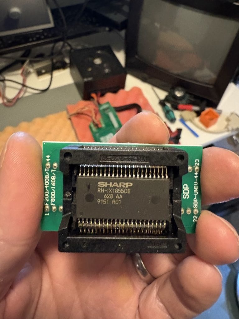
My initial guess was that it might be that the system failed to boot due to problems with the boot ROM, and that’s fairly easy to check. I desoldered the ROM with the BIOS and verified it against existing dumps in MAME.
Everything looked good, so this didn’t seem to be related. The memory area where the IPL (BIOS) lives matched the existing dump perfectly.
Probing around CPU and RAM with Logic Analyzer
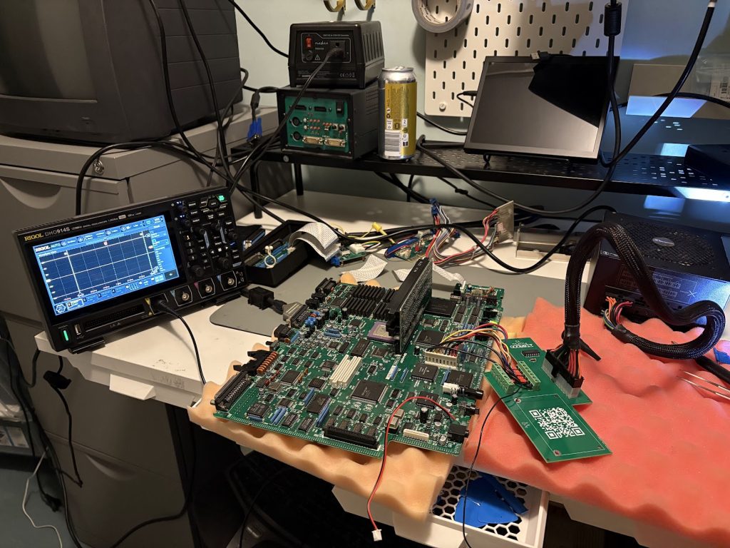
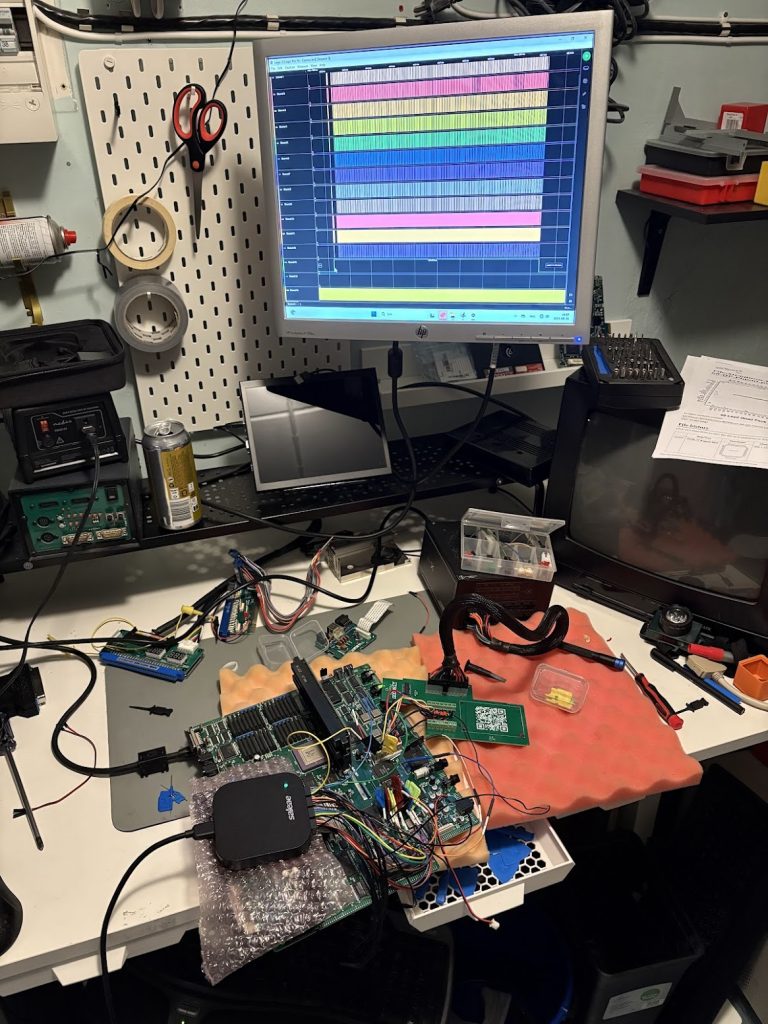
I then took out the oscilloscope and started probing the CPU pins to see if anything looked unusual. It became clear that HALT was being asserted after only about 1ms, which after some digging into the datasheet either indicates that the CPU is trying to execute an illegal instruction, or that some other device on the motherboard asserts the HALT pin.
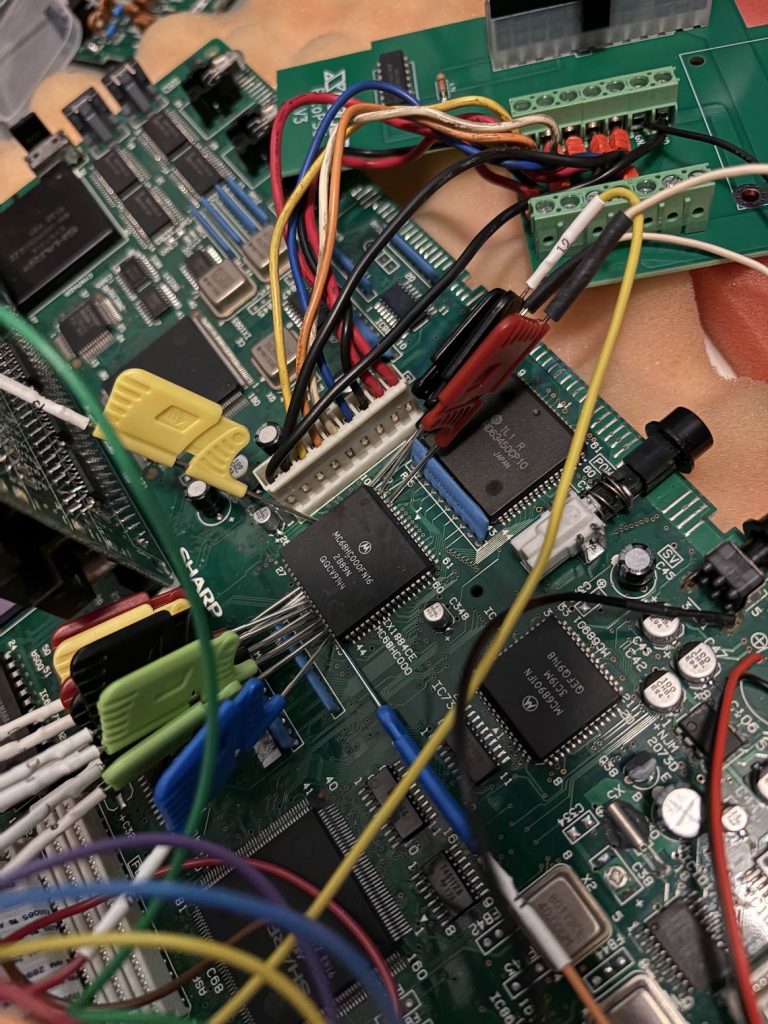
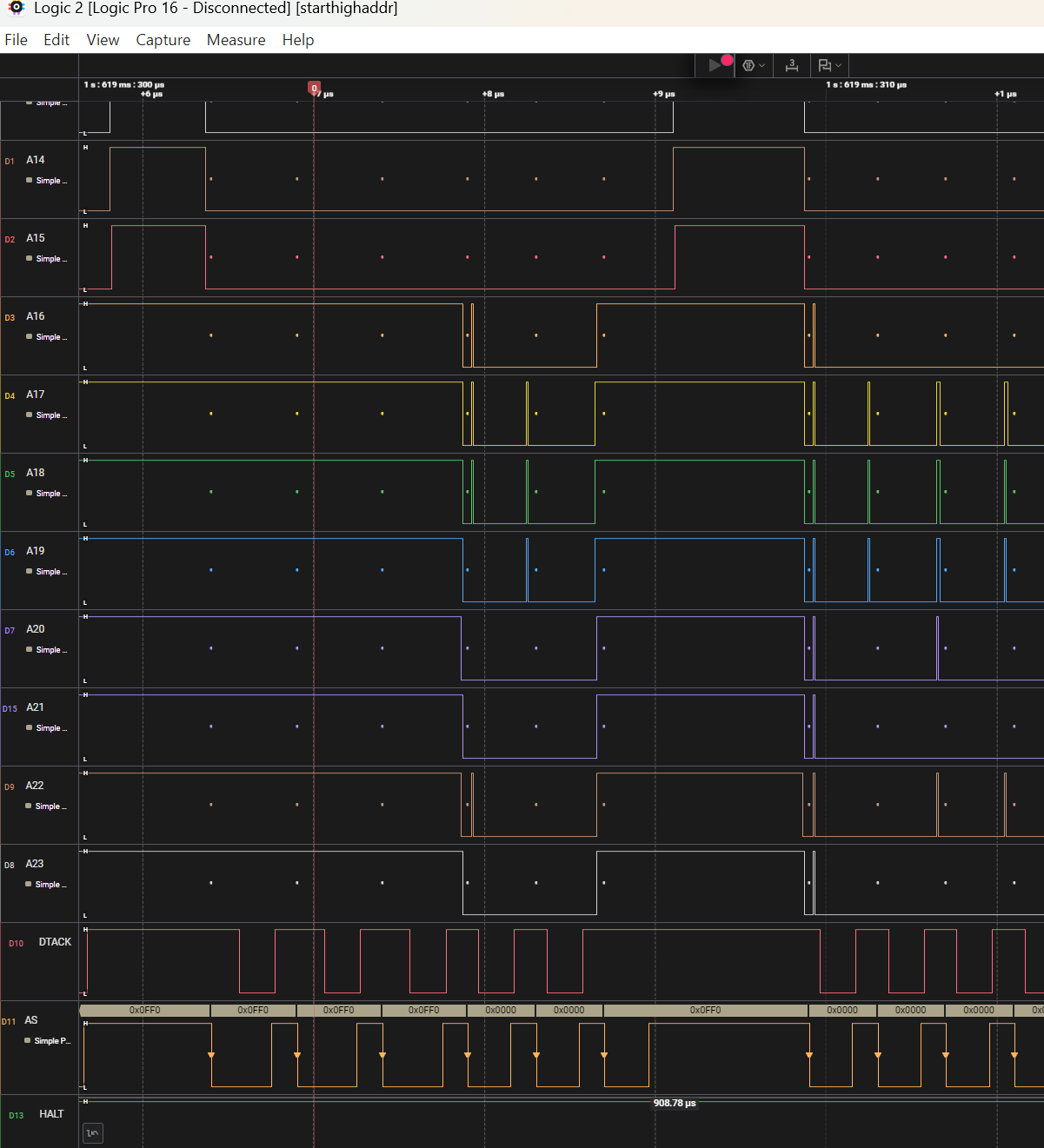
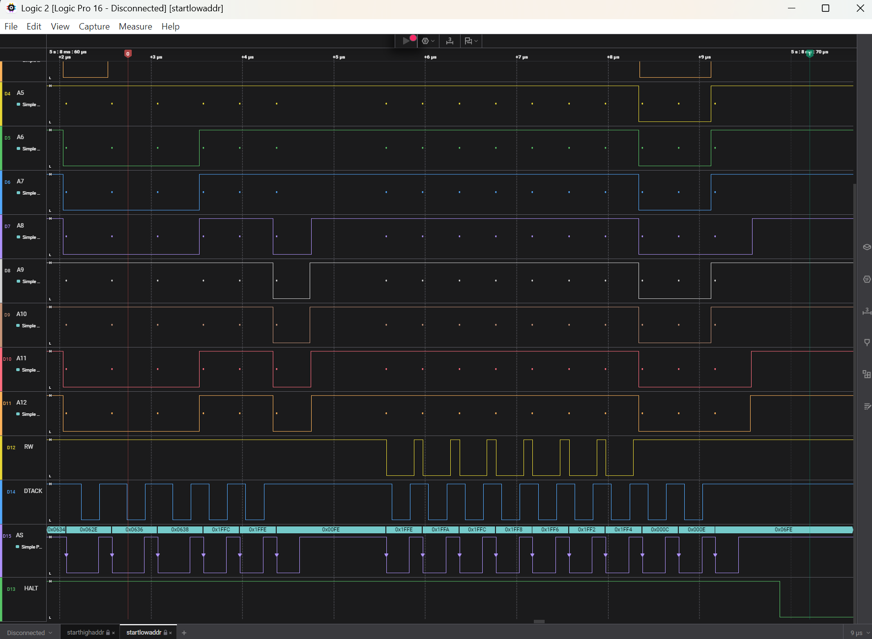
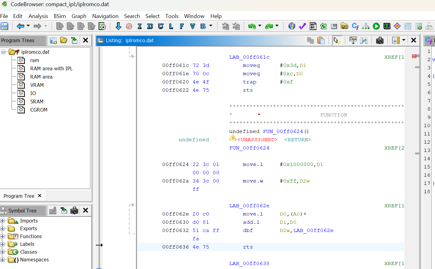
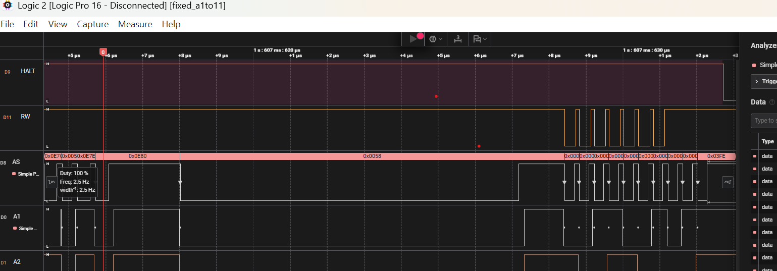
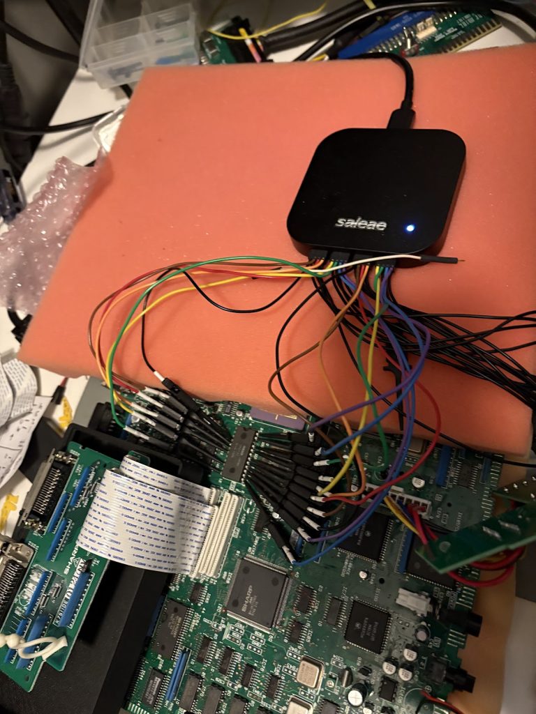
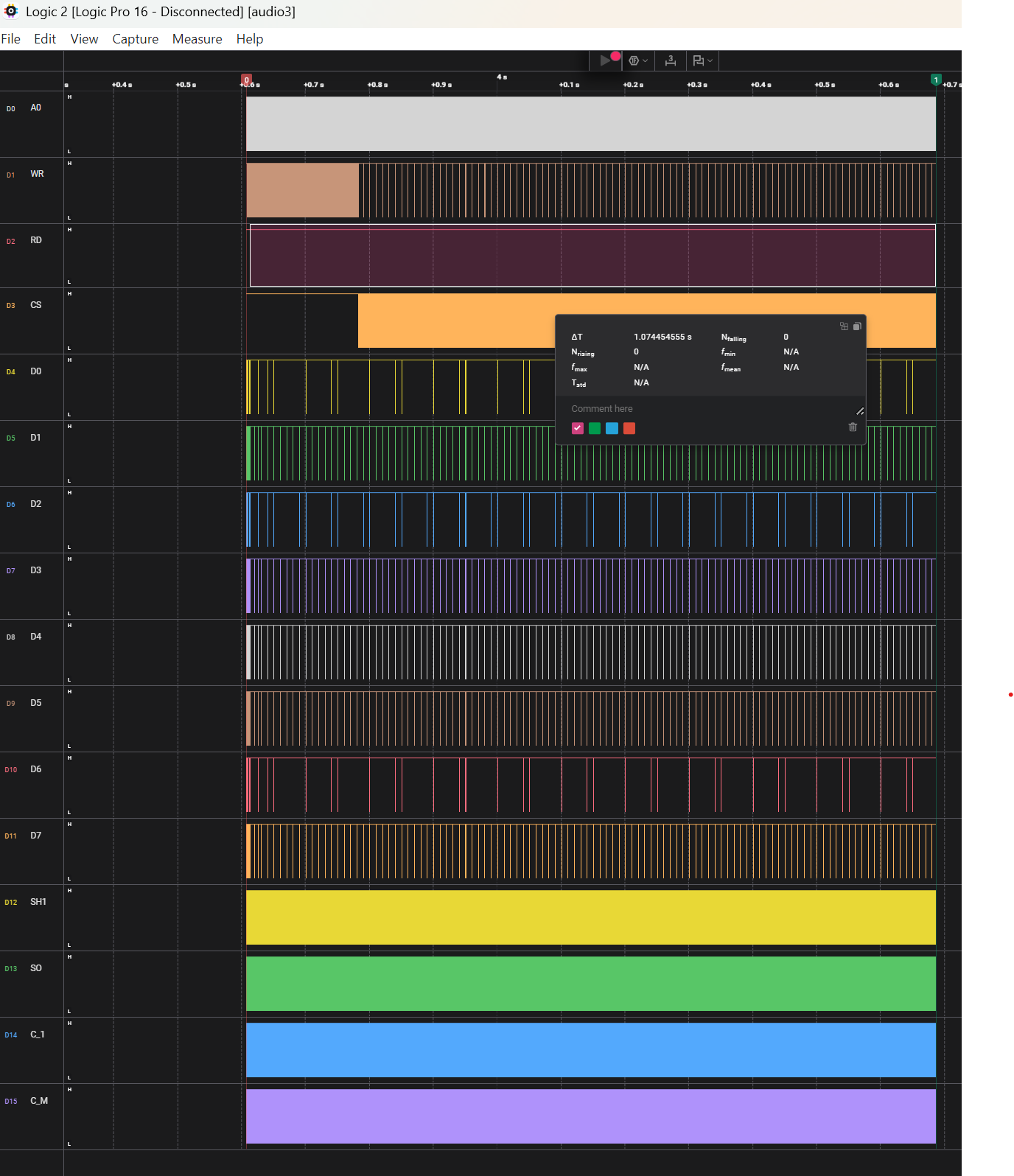
When connecting a Logic Analyzer (Saleae Logic Pro 16) to the CPU address bus, I could see it failing after a read of FF0636 where it would start failing. Decompiling the BIOS in Ghidra shows that this is a RTS instruction, which means it tries to get the return address from the stack in RAM which supposedly fails. When probing the RAM, I could see that only two of the four RAM chips were getting CS pulses, indicating that something was broken there. The lower byte was being read but not the higher one.
Since this logic analyzer only has 16 channels, I could not fit the entire Address bus when looking at things, so I had to do multiple sweeps to both check the high range being accessed, and then the more exact position. Since the failure was reliable, this was fairly doable, but if I had 32 channels things would be a lot easier.
To illustrate this further, the first image below shows that the Address has the higher bits set to 0xFF0, and the second image shows 0x636 (and 0x638) for the lower bits.
I do recommend this logic analyzer in general since the software is really great, but for these particular usecases with large address buses, I would probably have preferred something with more signals.
(Detour) Forcing 16-bit reads/writes
Since X68000 is a 16-bit machine, I naively thought that I could just tie the CS signals of all four RAM together (lifting the CS pins of the higher 8 bits), which should allow the code to read the return address from the stack correctly…
… and this worked! Kindof. Instead of halting after 1ms, it would now halt after about 22ms instead.
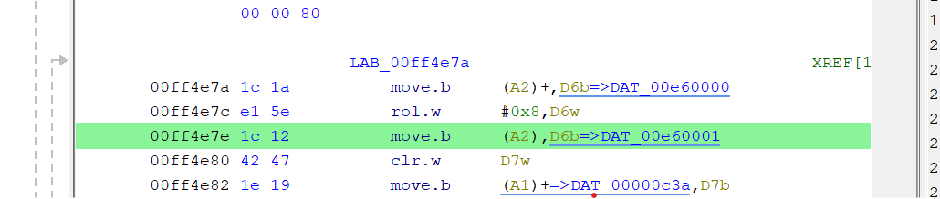
Connecting the logic analyzer again shows that it now crashed at FF4E7A which is the first time a move.b instruction is executed to read from an uneven RAM address, doing a 8bit read instead of 16. This one asserts UDS but not LDS, meaning that my forced 16-bit reads would not work since they assumed LDS was set.
I did try to work around this by also doing 16-bit reads for these, but then realized that 8-bit writes would now also write the byte that should not be written, so this was a bit of a waste of time.
Actually figuring out the RAM issue
Since no schematics for this exact model exists, I had to do some guessing based on other X68000 schematics, but managed to locate how the LDS/UDS signals are tied to assert the CS on RAM (through the ASA Custom IC).
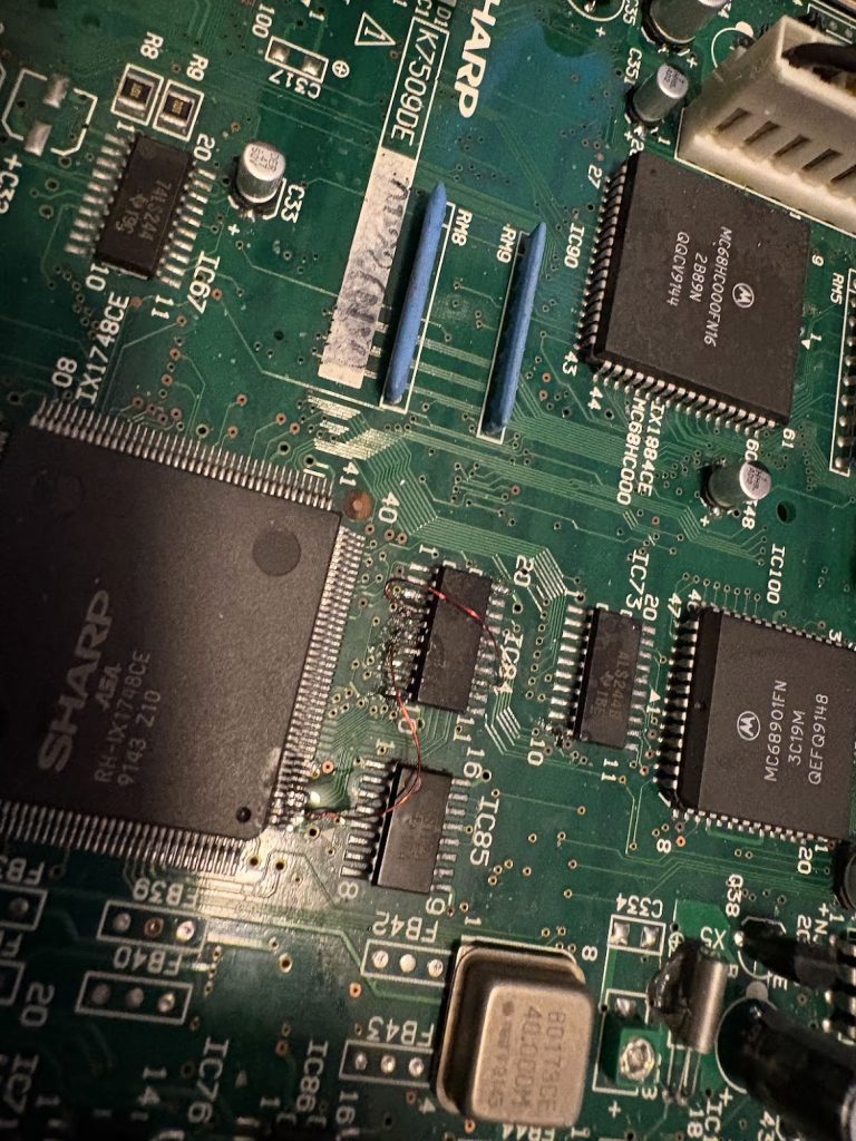
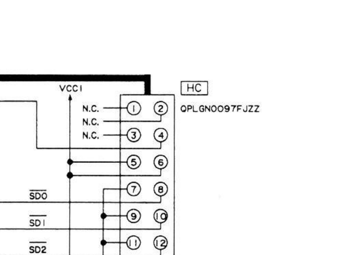
LDS and UDS go to a buffer at IC84 which connects to the ASA. The buffer itself seems to work fine, but the ASA was not getting a signal for one of the bytes, which seemed to indicate trace damage. From looking at the schematics for non-compact XVI, I patched this up and now the system would boot! Two traces were apparently busted.
Ignore the flux that hasn’t been cleaned up below. It’s fine now 😉
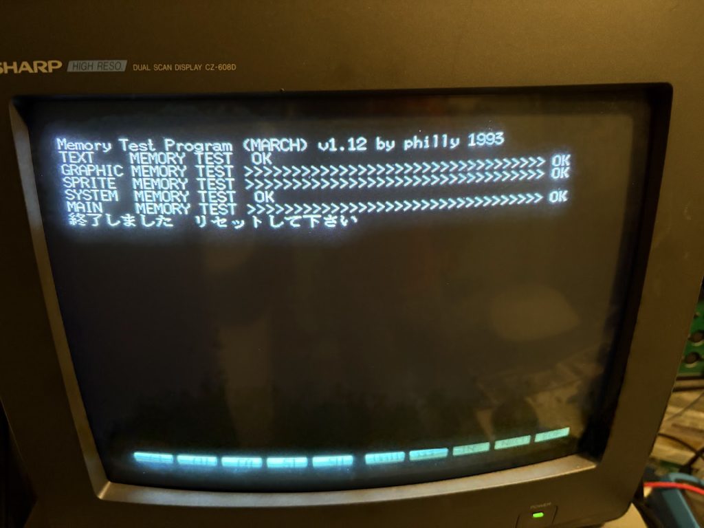
I could now run memtest from SCSI HDD and verify that the system looked OK!
Stuck again when booting games
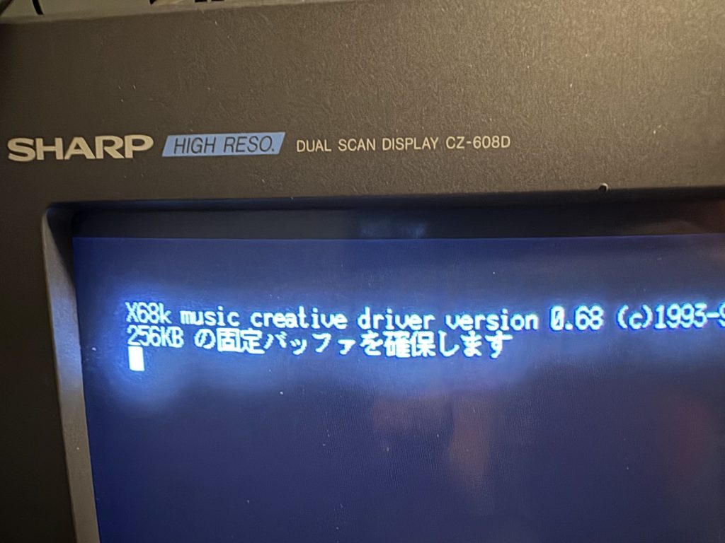
Floppy drives seem dead, but I could boot a SCSI HDD image now, but when trying to start games, I would get stuck when loading the sound driver.
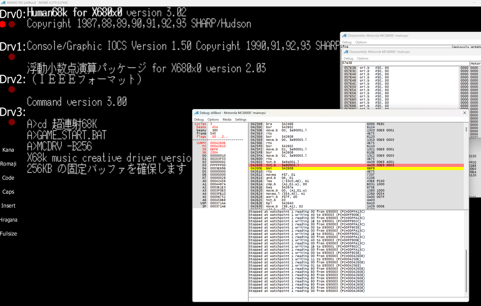
When looking at this in a logic analyzer, I could see that the CPU was not in halt, but repeatedly trying to read from E90003, which is the address space of the FM audio. Looking around the relevant code in an emulator, this seems to be a loop which repeatedly reads from there until a non-negative value is returned.
042608 tst.b $E90003.l
04260E bmi $42608
… so something else is busted
Fixing the FM audio
I connected the logic analyzer to the FM chip and noticed that despite CS being asserted, RD was stuck high (WR would trigger along with CS though).
This seemed to be fed through a 47LS486 which is a real weird chip without much info… except from in the x68030 compact data sheet where a description exists. In practice, it will just act as an inverter for WR. The relevant output seemed busted though, so I solved that by slapping a LS00 NAND gate on top of the buffer for the relevant signals (while lifting the pin from the 47LS486)…
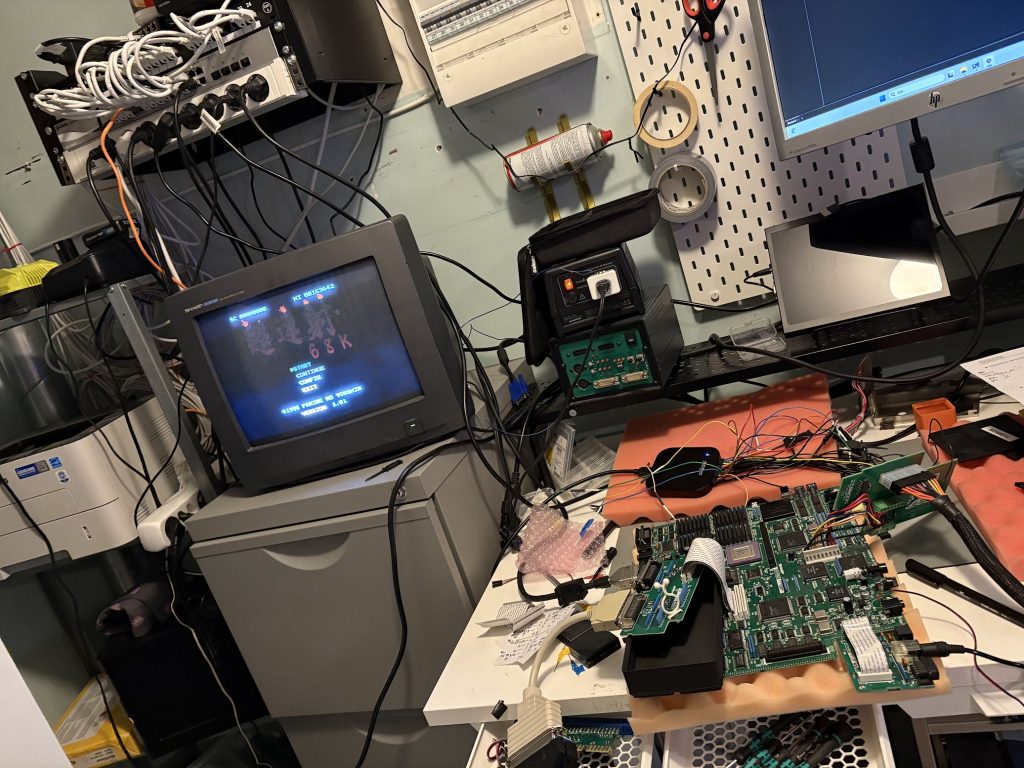
… and this worked! Games now boot and runs flawlessly!
Replacing the PSU internals
X68000 power supplies are usually problematic, and I don’t want to deal with stepping down 230V to 100V if I don’t have to, so I wanted to do a PicoPSU ATX conversion and drive the Compact from a 12V DC adapter.
There’s many ways to do it, but I had spare PCBs of the PicoPSU V3. These don’t really fit in the Compact PSU case, but some violence later and things were in place. The parts that were broken off are related to soft power only, and don’t carry any real current.
Then there was just the puzzling together of parts…
Everything works!… kindof
Now the Compact boots games and plays them fine, but there’s still some lingering issues. 16Mhz mode doesn’t work, and neither does the floppy drives. In practice I don’t think I really want to deal with floppies when I can SCSI boot so that’s pretty much fine. Having 16Mhz mode work would be nice though. When enabling it, the 16Mhz LED handling works correctly and the CPU gets the right clock, but still it wont boot. For now I’m ok with only running on the “default” X68000 speed though, but maybe I’ll go back to this later.
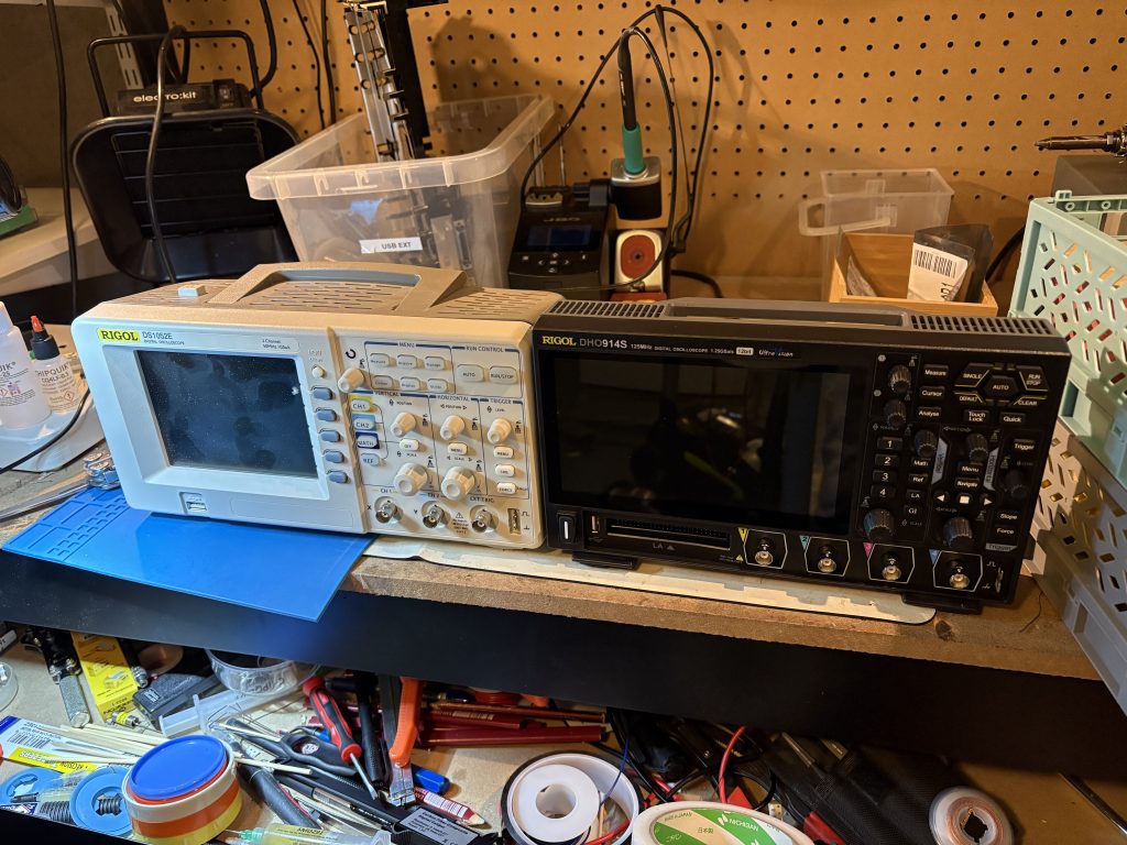
After having used my old Rigol DS1042E for about 11 years, I finally upgraded to a fancier 4 channel scope.
Picked up a Rigol DHO914S which also will replace my old junky aliexpress function generator.
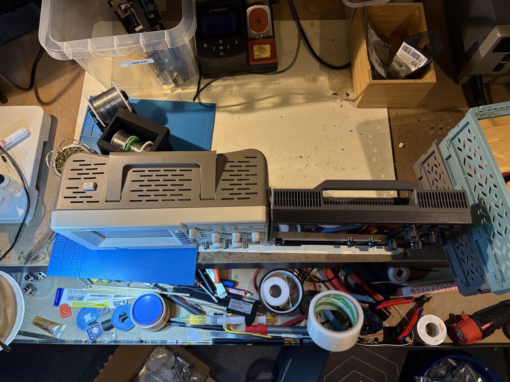
The newer Rigol scopes sure are tiny! I guess this is partly due to the PSU no longer being internal. Very cute.
Haven’t had time to test run this thing much yet but seems pretty nice. Startup time is crazy long when not using sleep mode though, but I guess I’ll have to live with that.
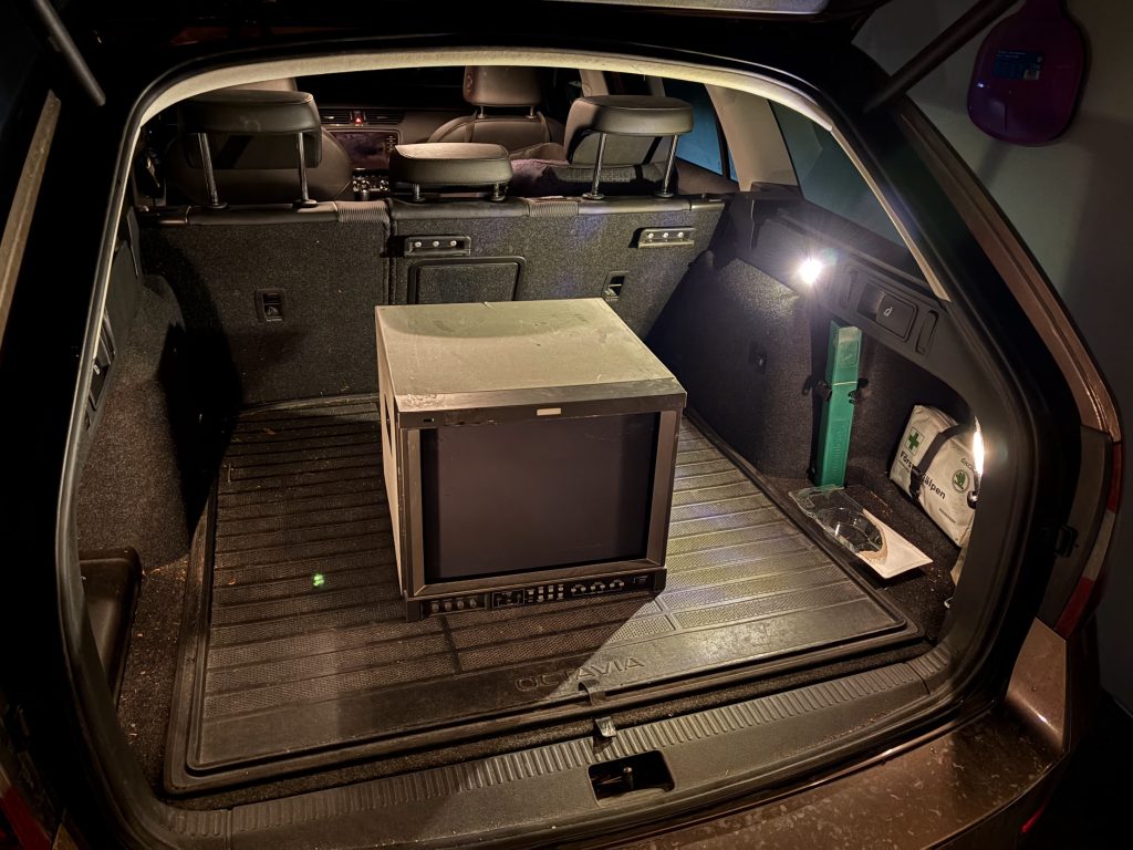
A month or so ago, someone was selling a broken JVC DT-V1710CG for quite cheap an hour or so from here by car. These are quite exceptional pro monitors that work with everything from 15khz up to 720p/1080i high definition signal. They also handle 24khz from old Japanese computers very well.
Road trip!
I already own one of these, but would like to own another one, and my thinking was that having a working one as reference should help with repair (it did).
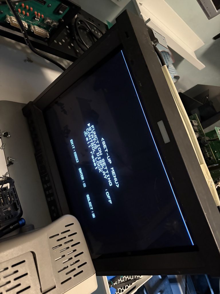
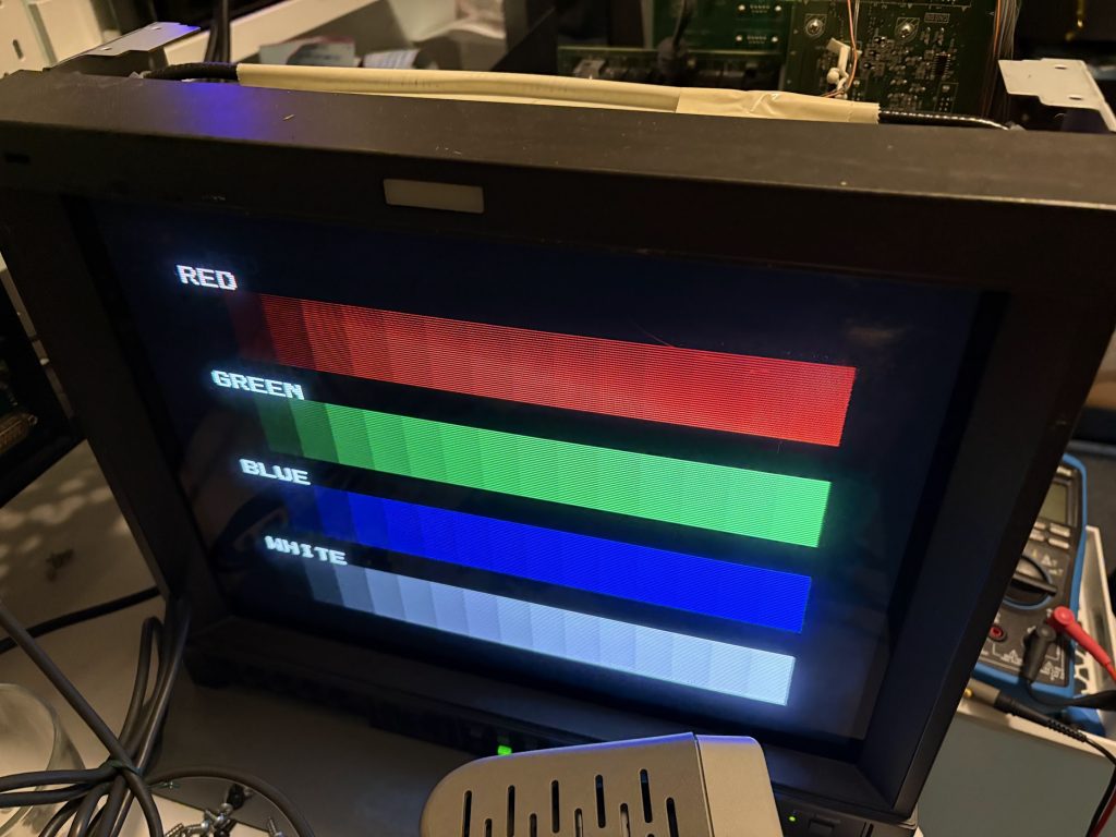
When connecting it up, it was indeed quite broken. Colors are completely messed up, and the beam wasn’t firing at all times leaving empty gaps in what was being drawn. Sync appeared fine though since picture was otherwise stable.
Poltergeists live here
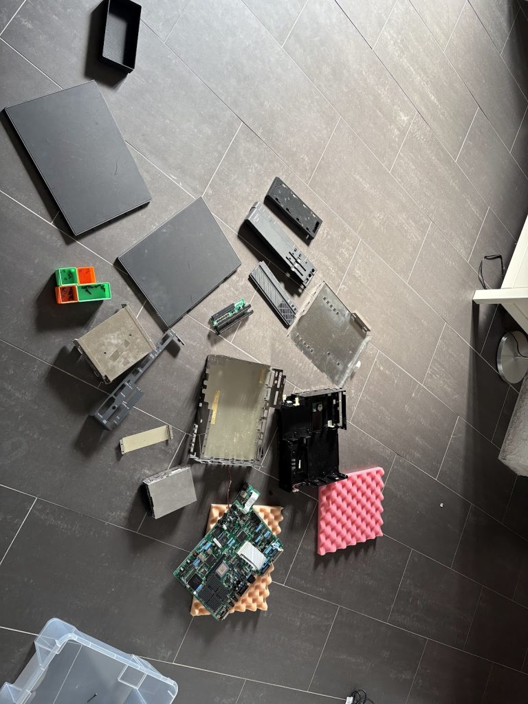
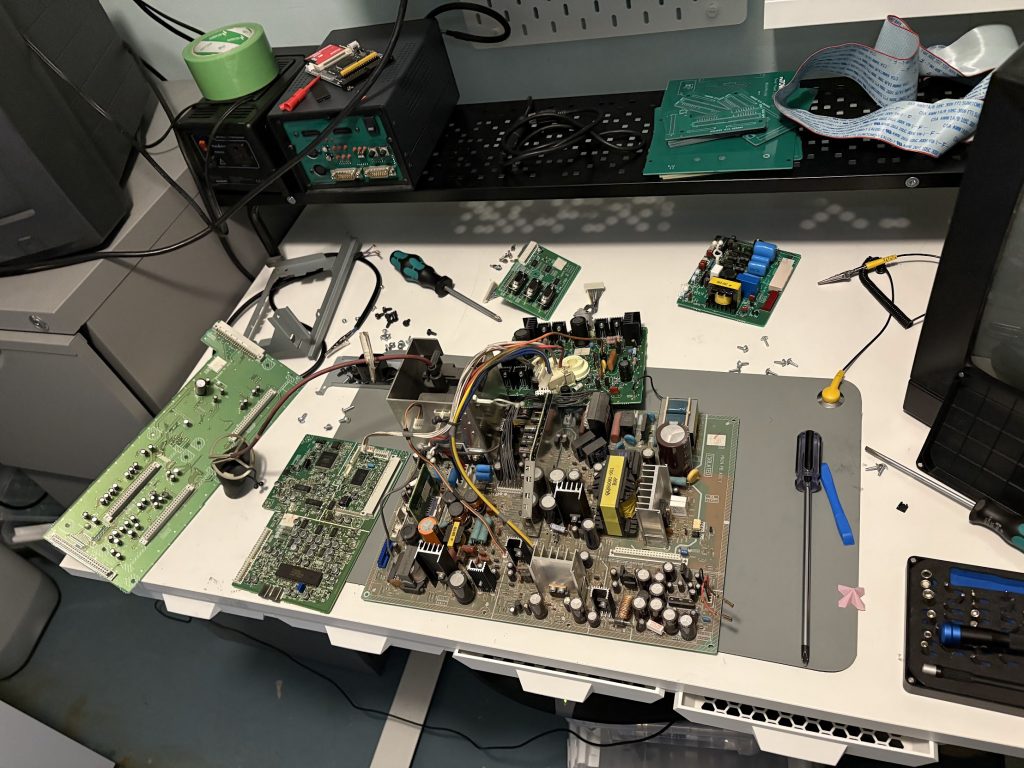
I started by dissasembling the entire thing to have a look at the internals for obvious things that could be busted. Overall, the condition of the internals wasn’t too bad. I had never dared dissasemble the existing one I owned, so it was also nice to learn how to do that.
Tube!Expensive puzzle!
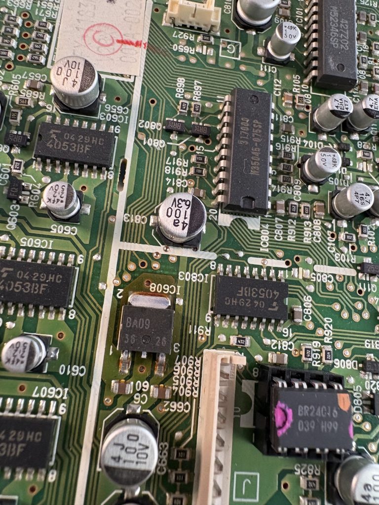
Something I noticed pretty quickly when taking it apart was that there was a burnt looking spot around a voltage regulator on the signal board of the machine. I made a note about this, and put the monitor back together again. Once mostly reassembled, I tried swapping signal board with my working monitor, and it became clear that this was the problematic board of the monitor, since image was fine once swapped (and the known working monitor started displaying same issues).
Swapping boardsWith working signal board
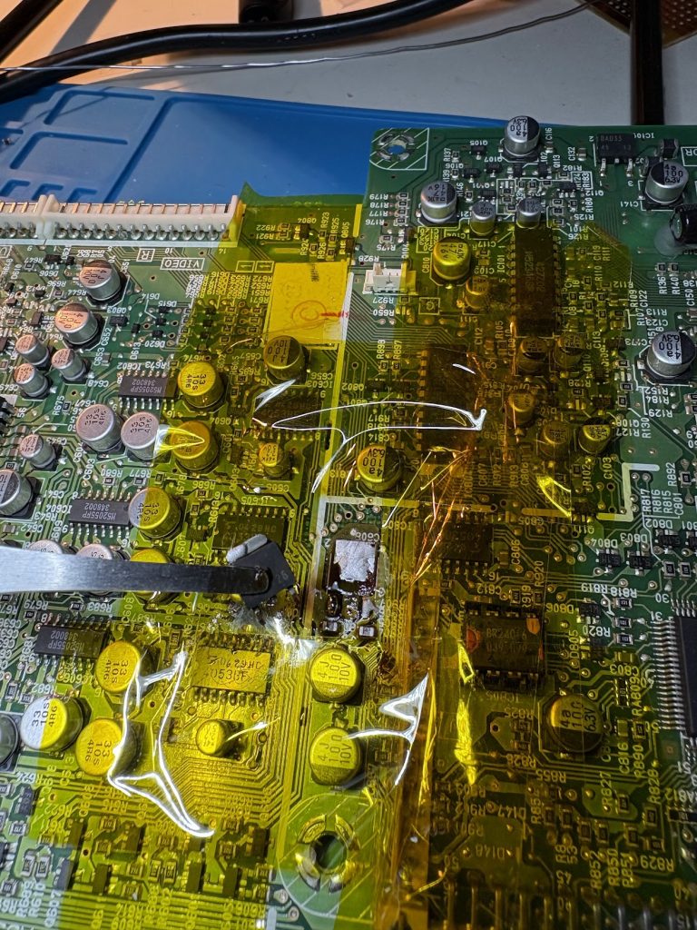
I desoldered the regulator and tested it on my bench, and it did indeed seem to be busted, pushing out higher voltage than it should. Swapping it out for another one did however not fix the issue with the image.
Burned regulatorHad to use hot air for these. It’s sortof a pain to do these replacements
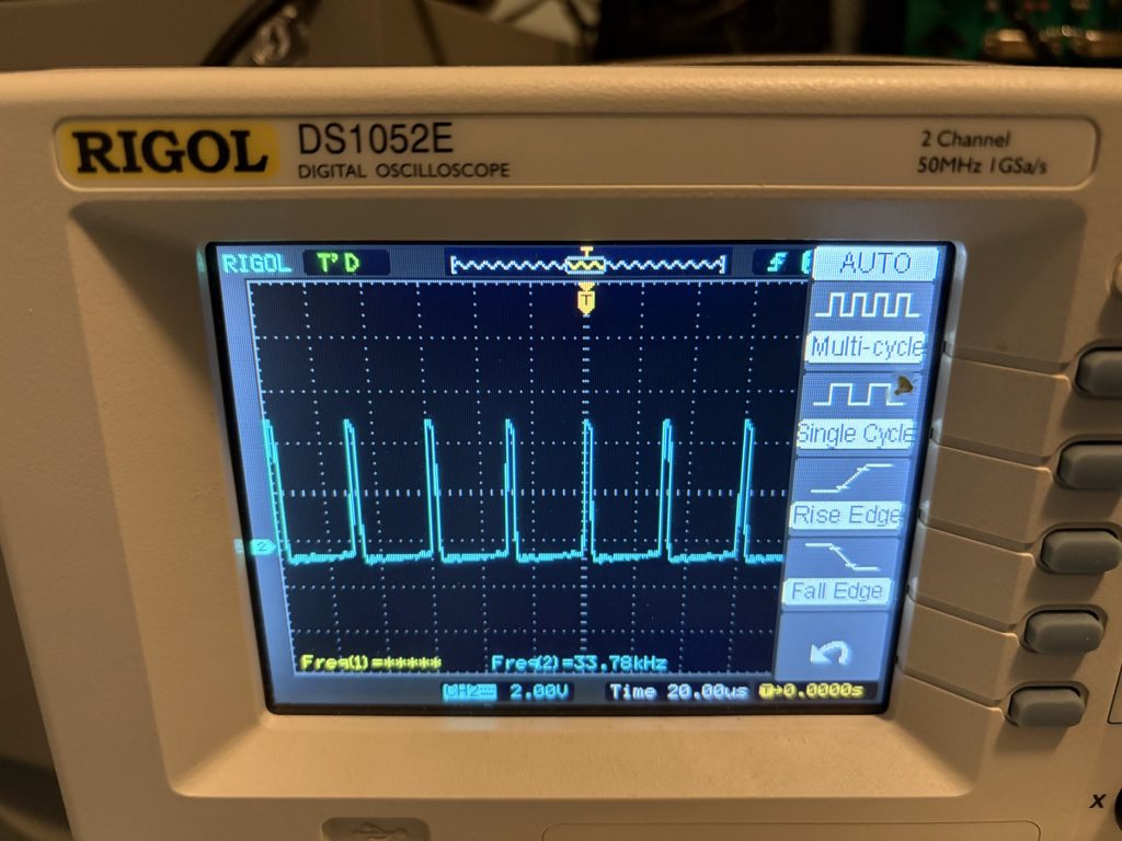
Scoping the HSync and VSync of the neck board showed that sync signals were indeed fine, and since the microcontroller seemed to function well with the menus, I assumed the problem would be somewhere on the area of the board housing the TA1276AN RGB processor.
Sync is fine
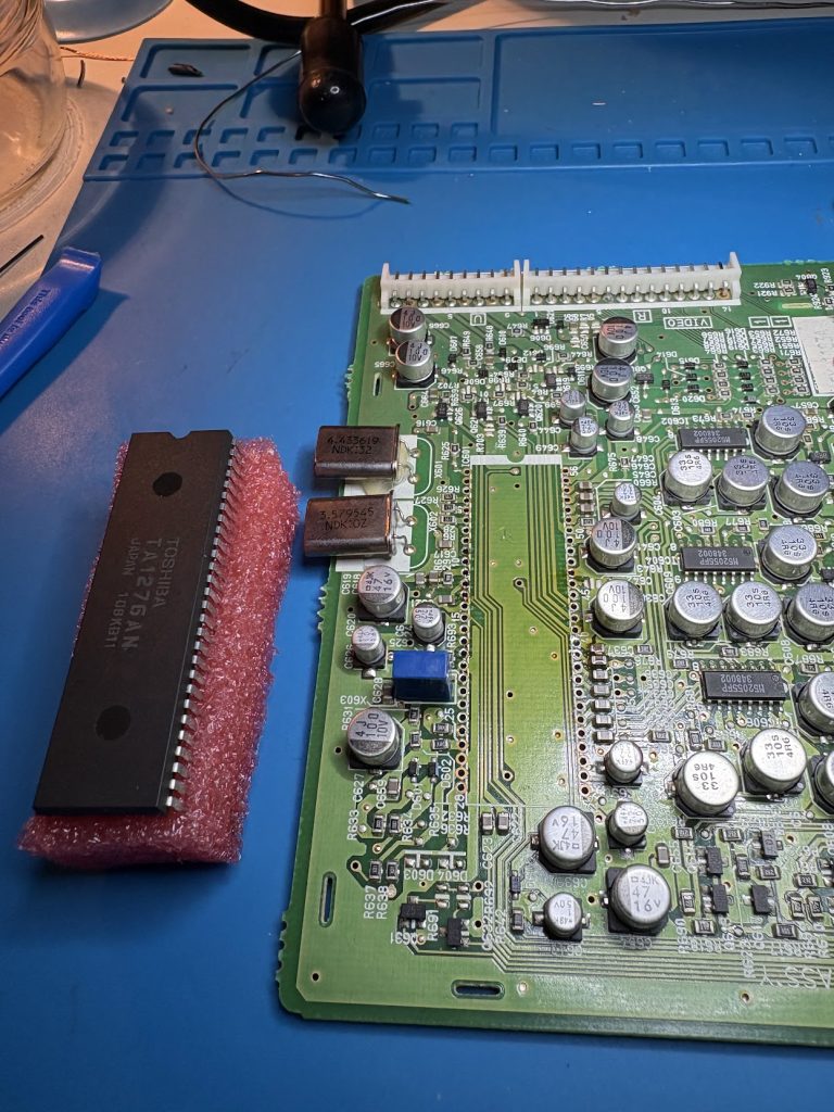
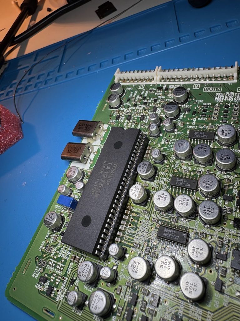
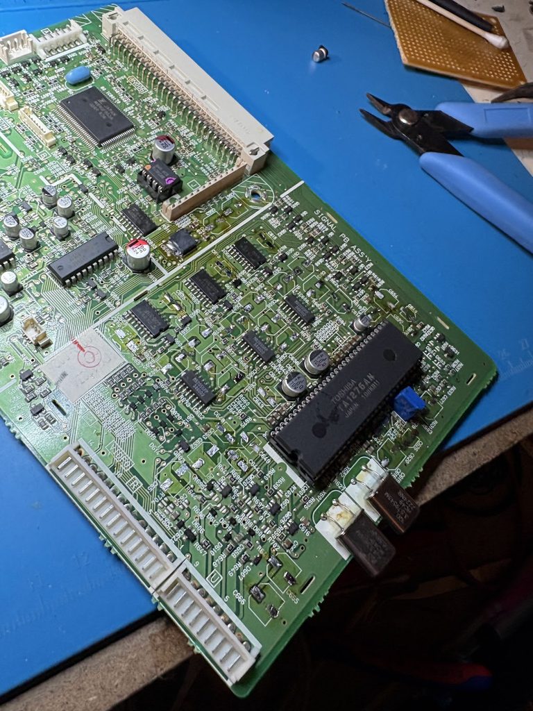
I initially thought that the RGB processor would be the faulty part, since the image was overall messed up and not just a single color being faulty, so I desoldered it, mounted a socket for a new one and sourced one on Ebay. This turned out to do nothing, so that was some wasted money and effort.
Desoldering these are also very awkwardNow with socket!
At this point, I wasn’t really sure which part was messed up so I scoped around a bit and noticed the crystals near the processors did not show stable oscillations. I decided to swap them and most easily accessible capacitors. In retrospect, it’s unlikely the crystals were at fault, but it was a cheap and quick swap so why not. I left some capacitors near the socket, since replacing those is very awkward (mistake).
No cap
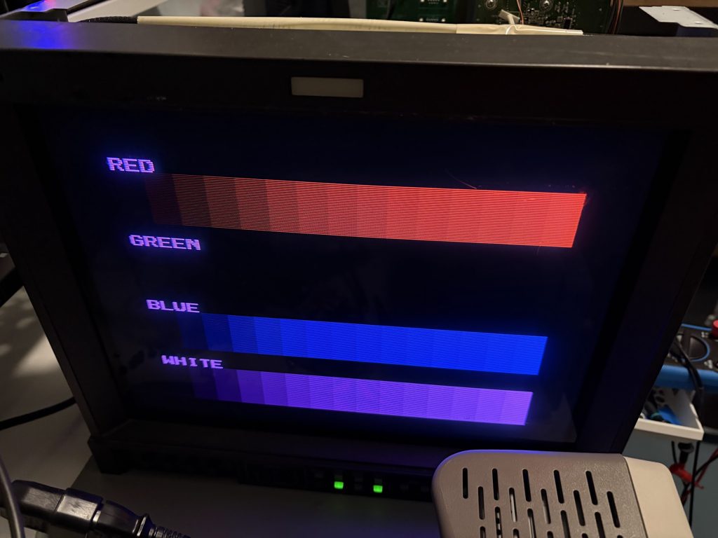
This recap made major progress. Image was now looking great… but lacked green. Scoping showed the green output being sortof present, but looking very different and lower in signal compared to green and blue.
No green 🙁
After getting sidetracked a bit looking for bad transistors, I realized that one of the capacitors I had not swapped was connected to “G S/H” on the RGB processor. Swapping that capacitor to a new one fixed the issue, so that one was definitely messed up. Likely at least one other significant one was as well which caused the other issue.
So many colors!
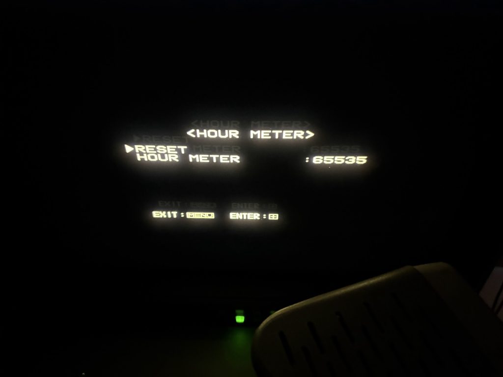
With it swapped, image is now very solid! Looks like this monitor has lived a hard life, since the hour count in service menu is maxed out 🙂
Counterstopped
I’m not very experienced working on CRT’s, so this was a fun project, and now I have a very nice monitor for my test bench!
This is just a small follow-up to the earlier posts, but I noticed that my Henkan Banchou was running real slow on my X68030 for some reason, so I tried swapping it for a old BlueSCSI V1 and that works much better.
I assume V2 would be the same, but this was all I had at home.
Some people seem to swear by Henkan Banchou, but it just wasn’t playing nice for me. As a fun thing, I’m trying out one of those Micro-SD card extenders now too, and routed that out the back of the unit. Makes it easy to swap cards, but realistically I don’t think I’ll do that much.
I’ll keep it like this for a bit and will then just use a regular Micro-SD card.
Later models instead use a LS04 which outputs clean TTL sync, which Extrons will happily eat.
Since these are mostly pin compatible, I assume it would be fine to remove the pull-ups resistors (R26, R27) and swap in a LS04 (IC3) into my CZ-600C, so I tried it out. The only 04 IC I had at home was a SN74HC04N, but I assumed it couldn’t really hurt to use that, and it did indeed work great, and my X68000 now syncs with my Extron perfectly.
On my model, the inverters of the IC are connected to a pin of the stereoscopic 3D port, and to the “Hig Res” pin on the LED board connector. The LED works fine after the swap, and I assume the 3D port should as well, although I don’t see myself using that.
I recently put together a Midiori MIDI card for my X68000, and the process was a little bit complicated, so I thought I’d write down a quick summary if someone else is interested in doing so as well.
Making the bare PCB
This one was straight forward, nothing special here.
Open midori.pro in latest Kicad, go the the board file and Plot the Gerbers (and drill files). I got some warnings about it updating files due to them being created in an older version, but looks like that didn’t matter much.
Zip up and send to board fab of your choice. I used JLCPCB.
I decided to be cheap and not use gold fingers or tapered edges.
Not much to say here. The FPGA has tiny pitch, so be careful and use magnification. At least on the revision (2.2 2020) that I soldered, U2 is oriented the other direction than other IC’s, so check for that.
Since I wanted to be able to have a SCSI to Flash adapter connected internally to my device, I had to make some adjustments to the hardware.
Hardware
I wanted to hook up an internal SCSI HDD to my X68030, and decided that instead of trying to manufacture a cable for this, I’d just make a quick replacement SCSI IO board with the proper connector. This board has the same configuration of resistors and capacitors as the original board, but lacks the external connector. It has headers for setting the SCSI ID, but it’s fine to leave this unpopulated and just use SCSI ID=0 for the X68030.
SCSI Device setup
Setup is quite minimal.
There shouldn’t really be any settings needed to be changed in SWITCH.X. Leaving device boot as STD works, and either 0 or 7 as SCSI_ID works fine.
I had a spare Henkan Banchou 変換番長 Pro from a previous project that I decided to use. I designed and 3D printed a bracket (STL is at end of this post) for this to fit in the top right of the X68030, since that’s where the internal HDD is in CZ-510C.
I loaded this with the SxSI-SCSI HDD Image v3.01 from NFG Games forum, and things pretty much just worked right away, once I connected the cable.
Power is supplied using the flat cable (as long as the connected device doesn’t require more than 1A).