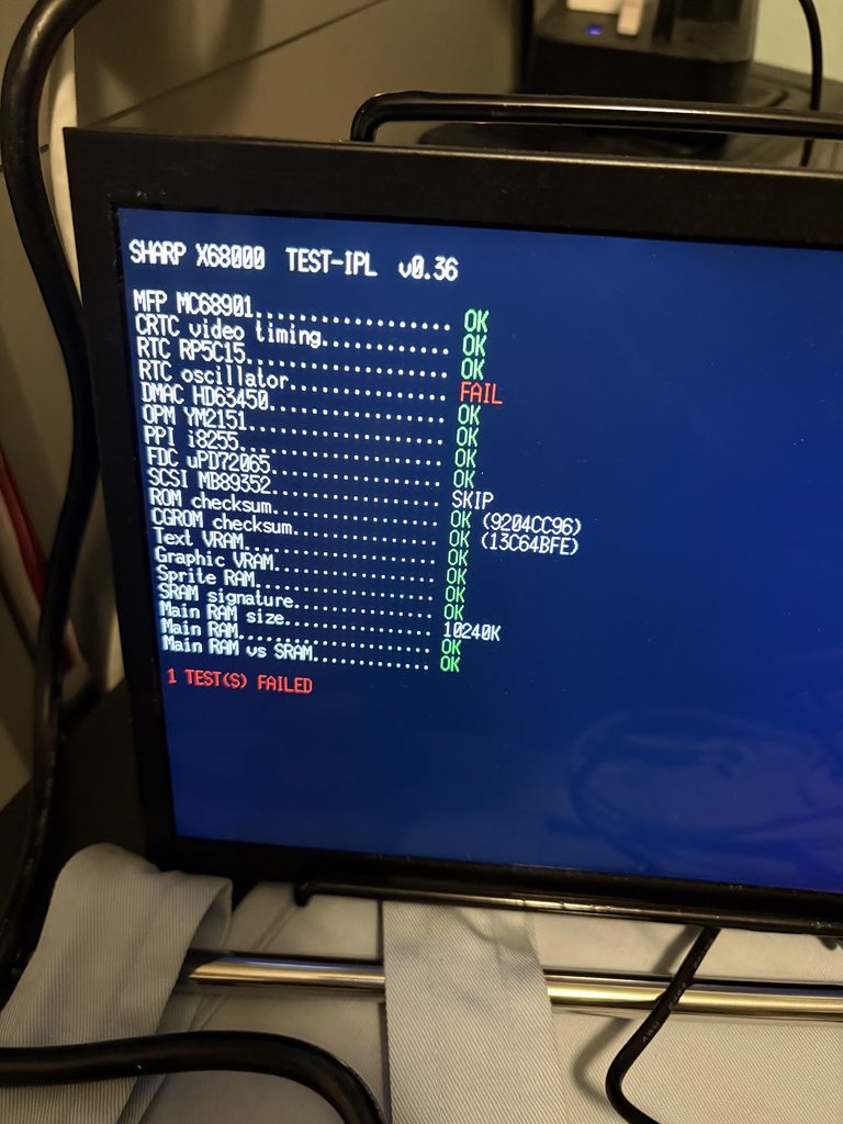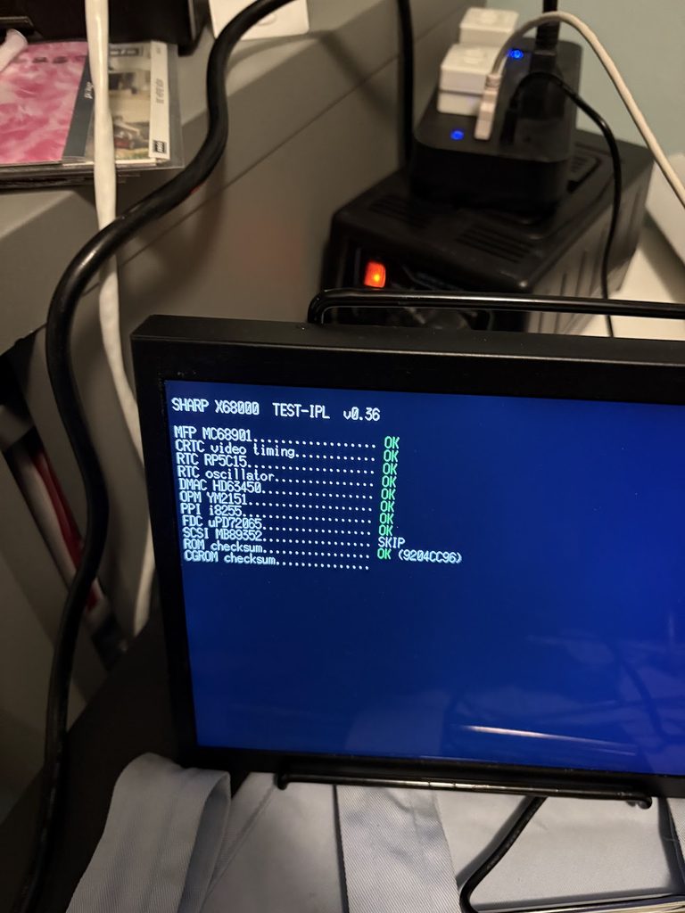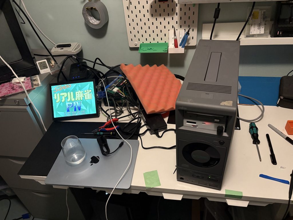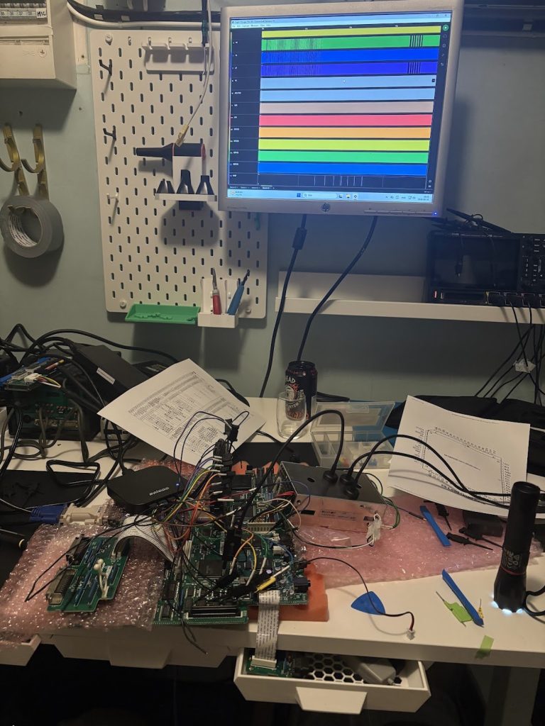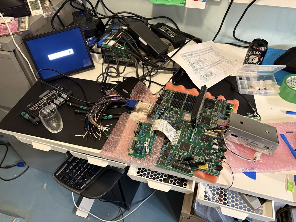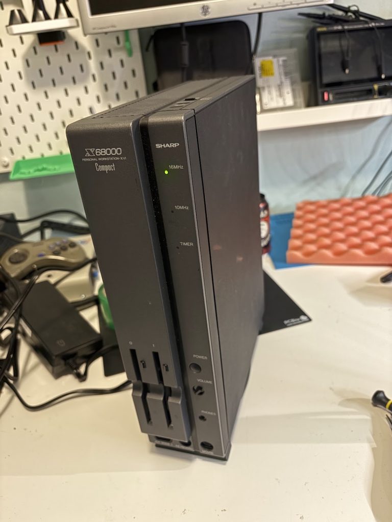

To use it, burn the IPL in bin/ to EPROMs for your X68000 IPL slots.
What this does
When starting the machine, this replaces the stock IPL (BIOS) with a systems test. Optionally, you can compile the Test IPL to boot into a real IPL once the system tests have completed. The default files in bin/ in the repo DOES NOT contain any Sharp IPL data, so you will have to supply that yourself if you want to do the chaining.
It will do some simple communication with various onboard peripherals, as well as run a memory test. See the repo for more details.
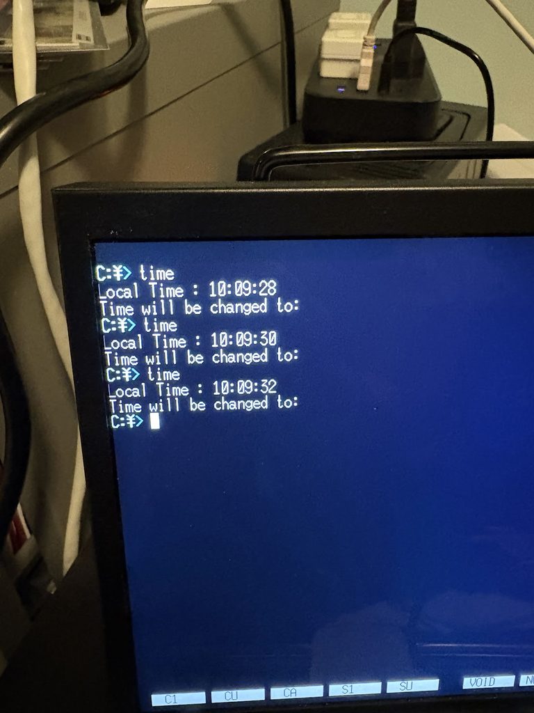
Finding an issue with the RTC in my X6800 Pro
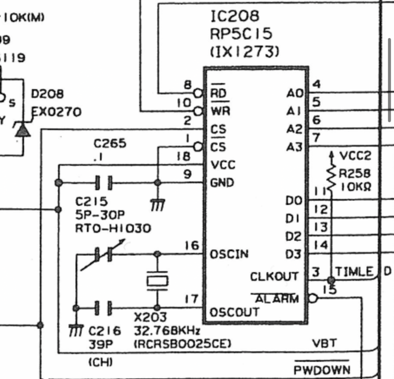
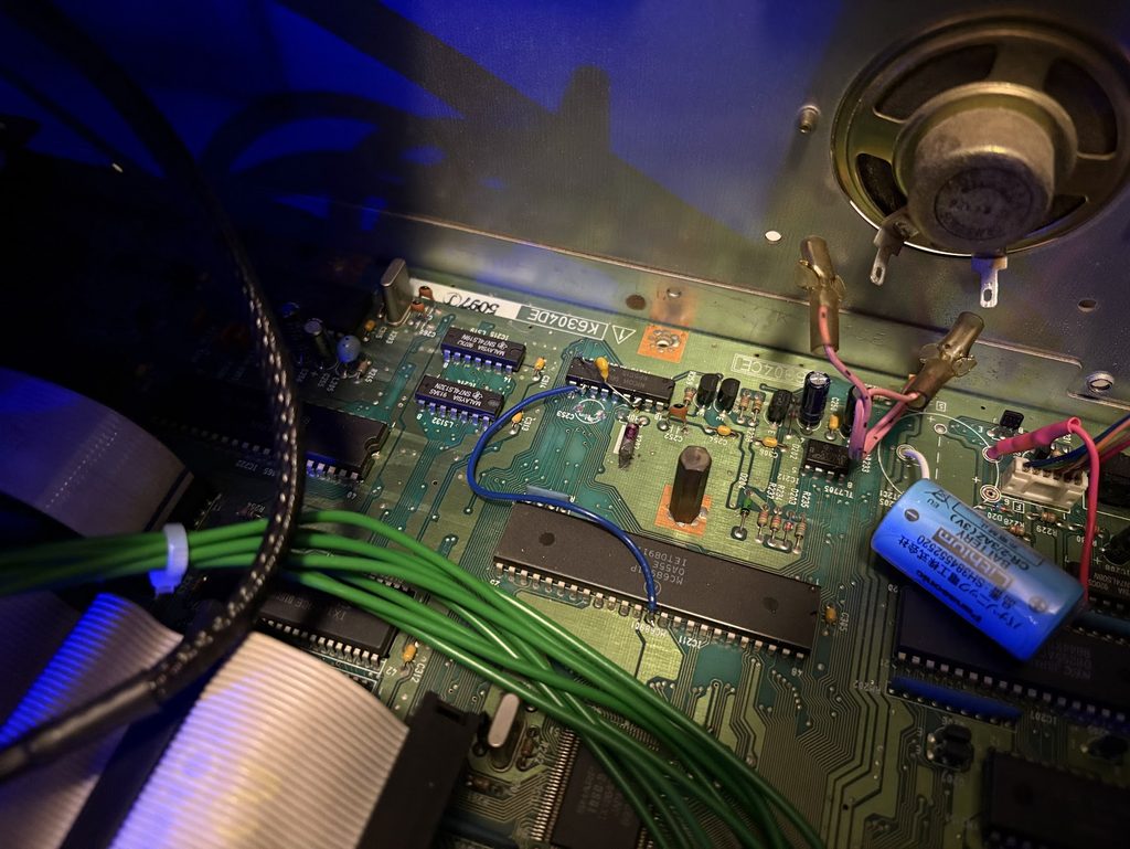
When trying this out, I noticed that the RTC Oscillator test was failing. Turns out this was a real issue, and time was not advancing. Some quick investigation showed that the variable capacitor near the RTC was busted.
We live in a weird time where we can talk to cloud robots and they spit out video game conversions for us. Everything is getting static recompilations and CV1000 games now even works on Mister.
Having worked as a software dev for close to 20 years, I dunno how to feel about all programming nowadays more or less using LLM’s. It’s hard to deny it’s pretty damn efficient at getting shit done though.
So I thought… guess it’s time to embrace the slop. Let’s make some dumb shit that I’d never do otherwise… and here we are.
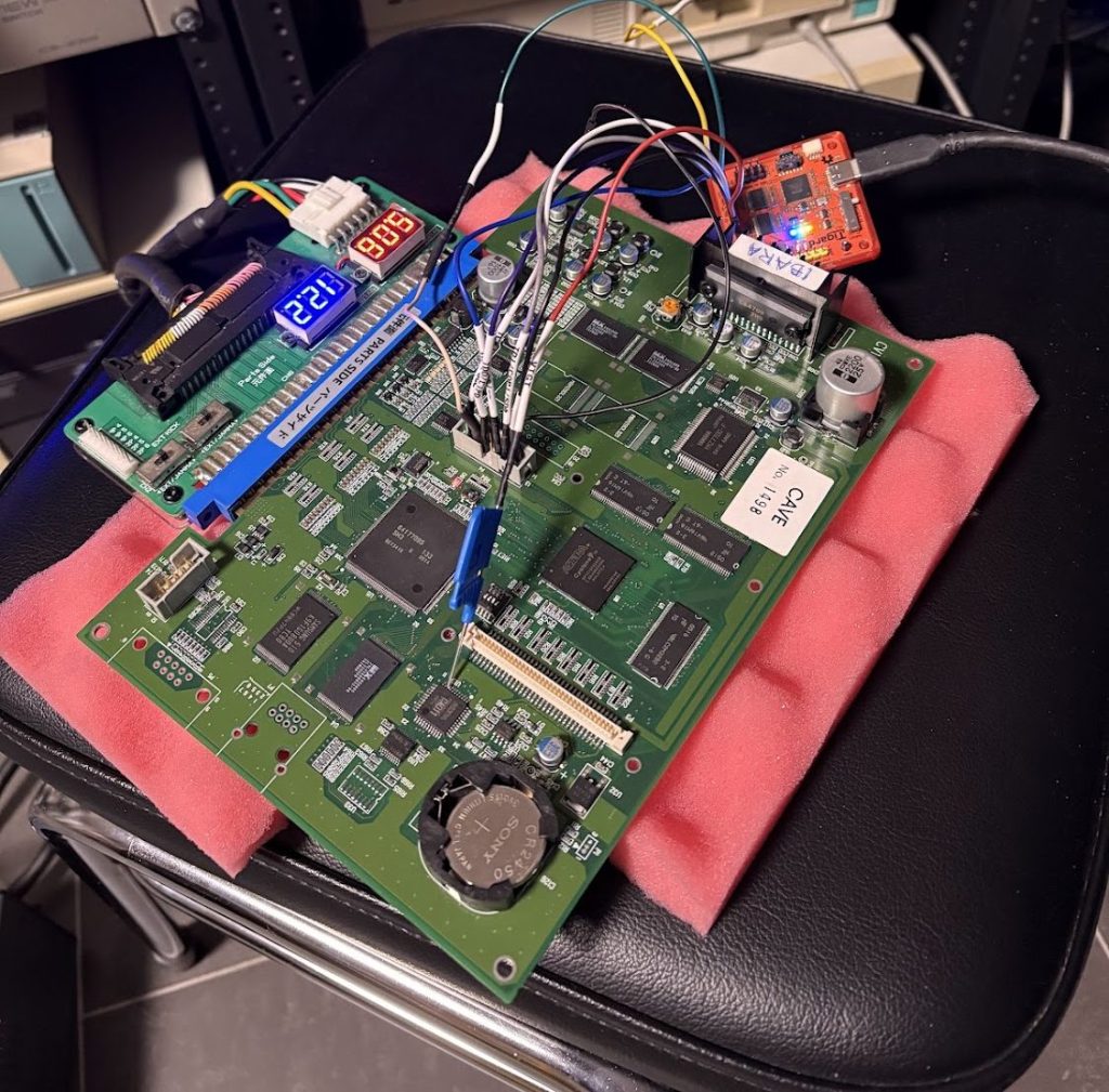
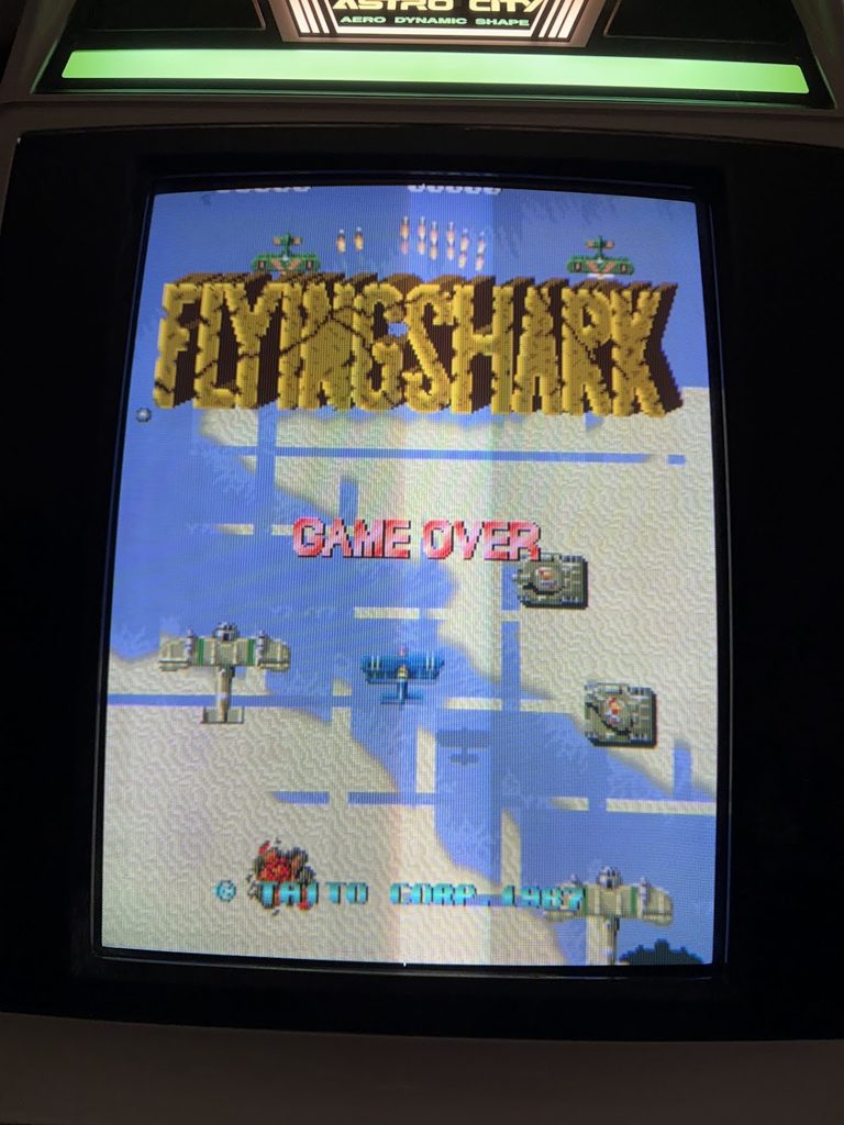
Enter, “Flying Shark : Slop Label”… which is Flying Shark running on a CV1000 PCB.
Slam that in a folder with fshark.zip, fsharkb.zip and ibarao.zip from the latest MAME romset. You’ll have to find those roms yourself you filthy fucking pirate.
Write out/fshark_u4.bin as U4 using JTAG to a Ibara PCB.
If you have one of the CV1000 multis, it will probably run fine on that too (not tested).
So… how did we end up here?
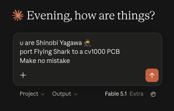
I just asked Claude to do it for me.
… OK maybe not entirely that easy, but also not entirely untrue. I threw this shit together with Claude Fable 5.1 in about a week of messing around on evenings.
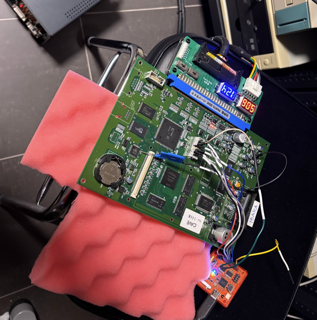
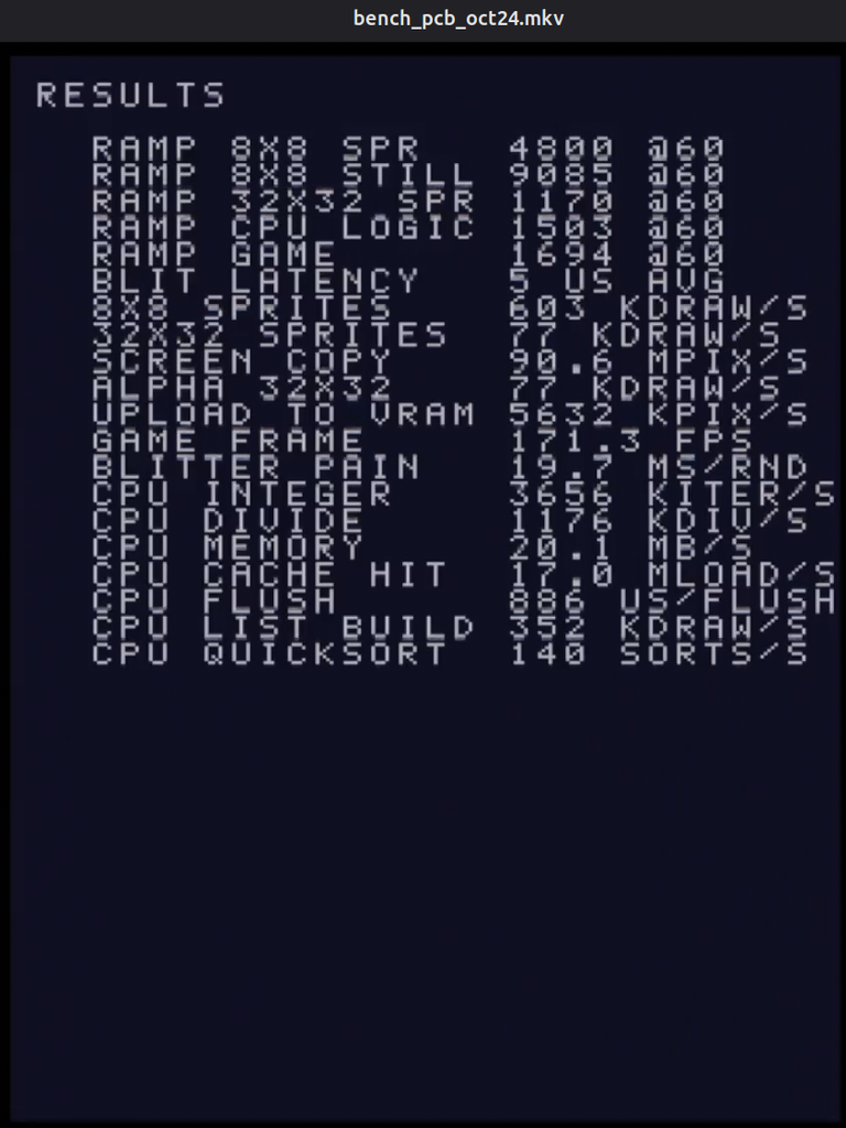
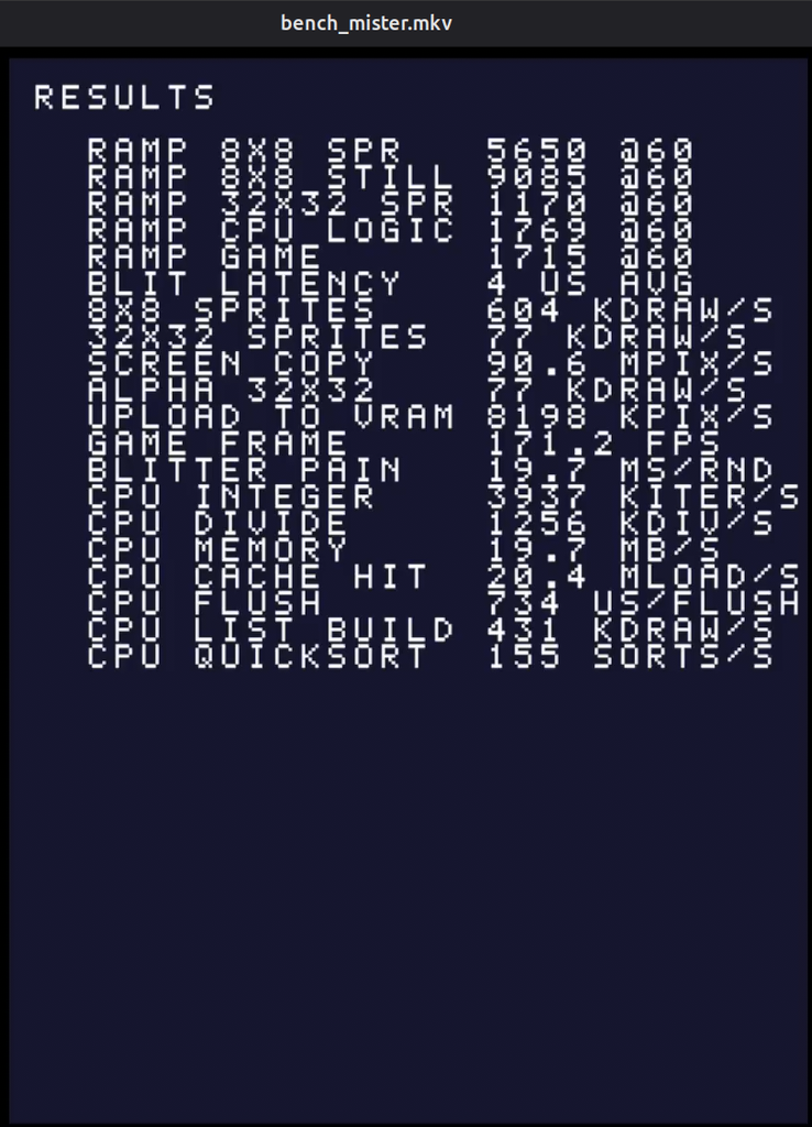
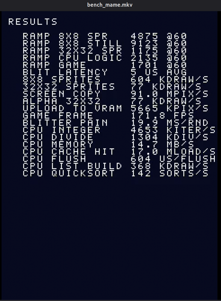
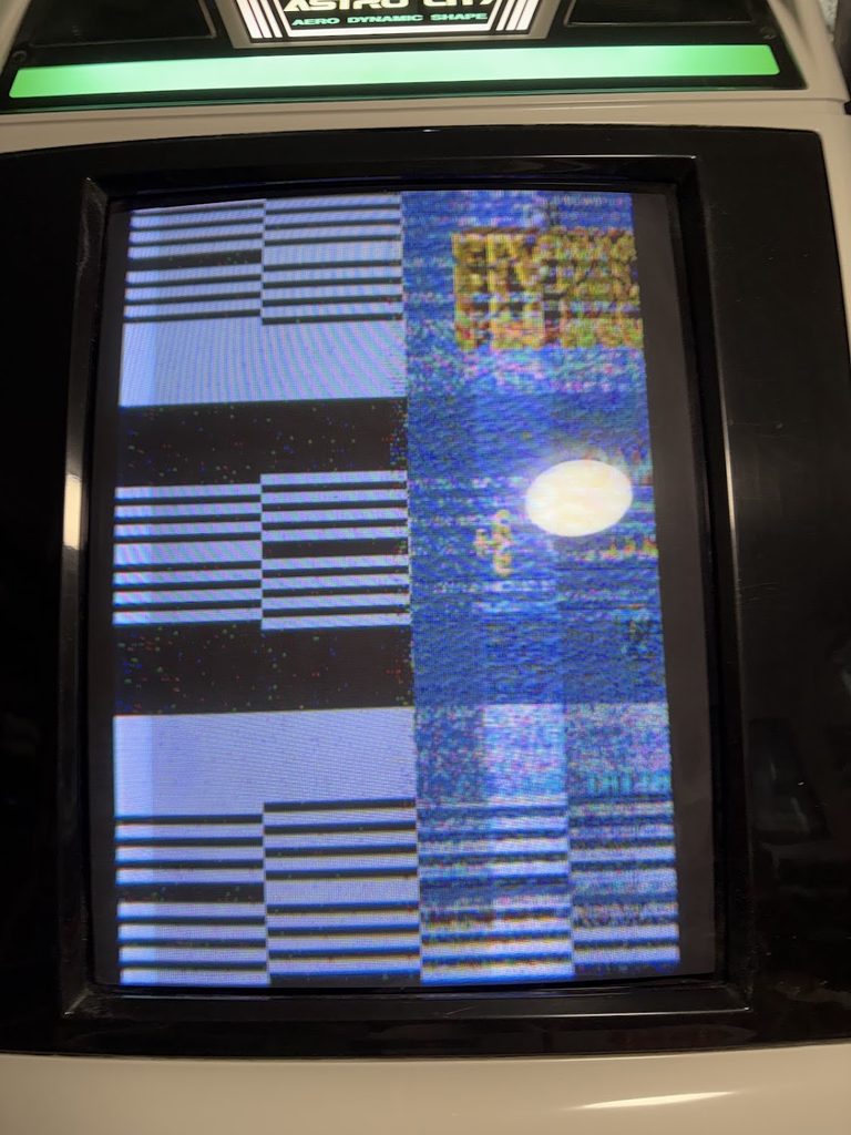
Getting things working with the cv1000 driver in MAME was fairly easy, but getting everything working on an actual PCB was unsurprisingly much harder. Early attempts had… interesting issues.
After lots of tweaking and iteration, graphics started looking better and better…
Eventually things looked great, but the game ran way too slowly (since after all the M68000 is basically emulated).
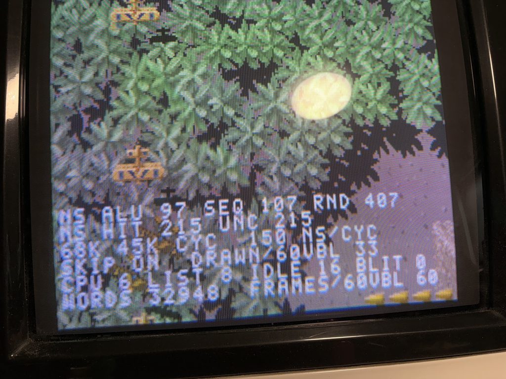
A few evenings of tweaking stuff, and testing things with various debug overlays, and things were MOSTLY playable though.
After a lot of trial and error, I ended up with something that plays fairly well! It will slow down on busy sections, but I’ll just pretend that it’s intentional CV1000 slowdown, since I know that’s what all the Cave sickos are into.
How does it run?
At startup, the Blitter from Ibara is injected into the EP1C12 used as Blitter, and the ROM is copied over to RAM, similar to how real CV1000 games do their booting.
Unlike regular CV1000 games, this port does not use the graphics RAM of U2 at all though. Since Flying Shark is an old small game, the graphics can live in U4 together with the code.
Each frame the following happens:
An M68000 emulator (Musashi) runs a frame of the program ROM.
All video writes (tilemaps, sprites, palette, scroll…) gets written to memory which gets translated to a command list for the Blitter. Uploads to VRAM only happen when a tile appears in an uncached color combination, or when a tile changes color.
Anything the original game hands off to the TMS320C10 math coprocessor just runs as native C code instead, rather than emulating that chip.
The Z80 Audio CPU is only minimally emulated, since the game ROM will wait for it. It’s not used for music playback. Each of the 25 sounds of the original game is mapped to a sound sample of the Ibara sound ROMs.
Controls are mostly directly mapped, but the port adds 10hz autofire for button 3 and 30hz autofire for button 4.
This version is slightly different from the other version(s) which have footage on Youtube.
I have dumped it. It is now available at archive.org.
Install instructions are further down in this post.
What is this thing?
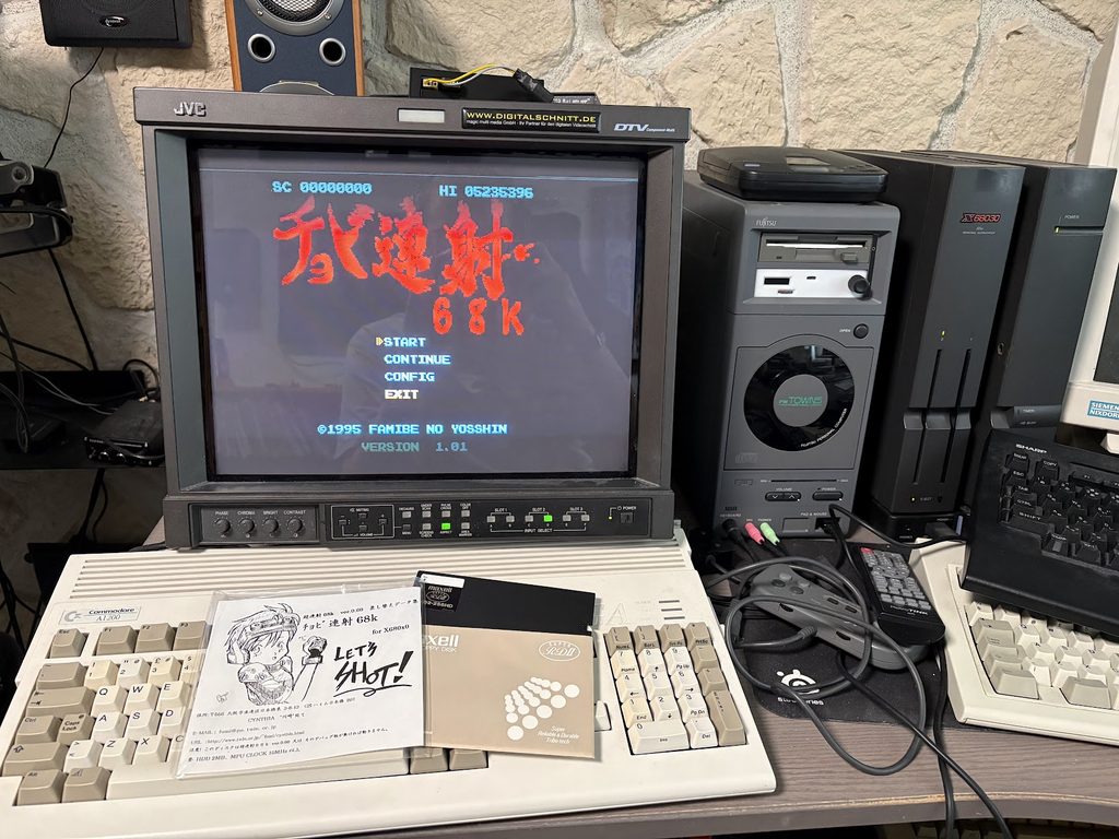
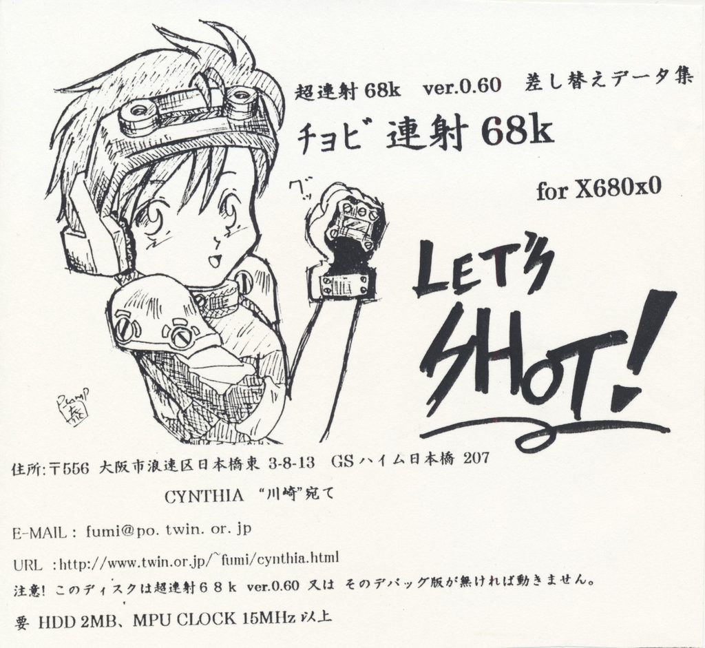
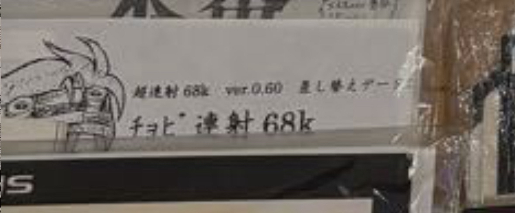
Chobi Ren Sha 68k is a conversion of Cho Ren Sha, which swaps out sound effects, boss sprites and music to other assets. Gameplay is unchanged.
It was created by Fumi of the doujin circle CYNTHIA in 1997.
The most interesting part of this release is that it’s semi-official, in that Yosshin apparently collaborated with the doujin circle that made it, and the original composer for the Cho Ren Sha music Loser Kachigawi wrote the music for this as well (this can be confirmed by looking in the dev diaries present on the floppy).
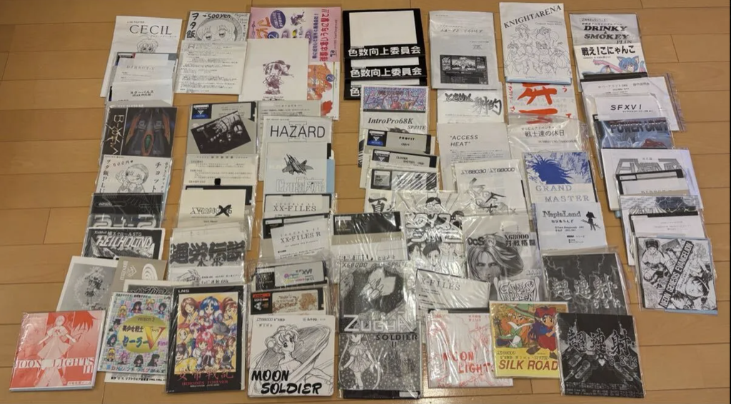
Somehow it has gone undumped until now. This is likely since I suspect not a lot of these floppies were sold, and I’ve only ever seen it up for auction twice. This one which I managed to snag, and in a huge doujin bundle a while back which went for too much money (see pic below).
The old auction I didn’t win
While this is a VERY niche release, as a big fan of CRS68k, I’ve been very curious about it, and it’s been a bit of a “grail” of mine to find.
Version differences
At least three versions of Chobi Ren Sha 68k exist. This one, which is a conversion that’s applied to an existing CRS68k 0.6 installation, a later floppy version for CRS68k 1.0, and then an even later CD-ROM release, which I believe also has a version for Windows (see discussion here).
Since this early version was made before Stage 0 was added to Cho Ren Sha, there is no updated Boss sprite in the 0.6 release.
One very fun find is that the Boss 1 BGM from Chobi Ren Sha 0.6 is actually a PCM version of the TLB music that was used in the 1.0 version of Cho Ren Sha! See video below:
Examples of some sprite differences between the versions:
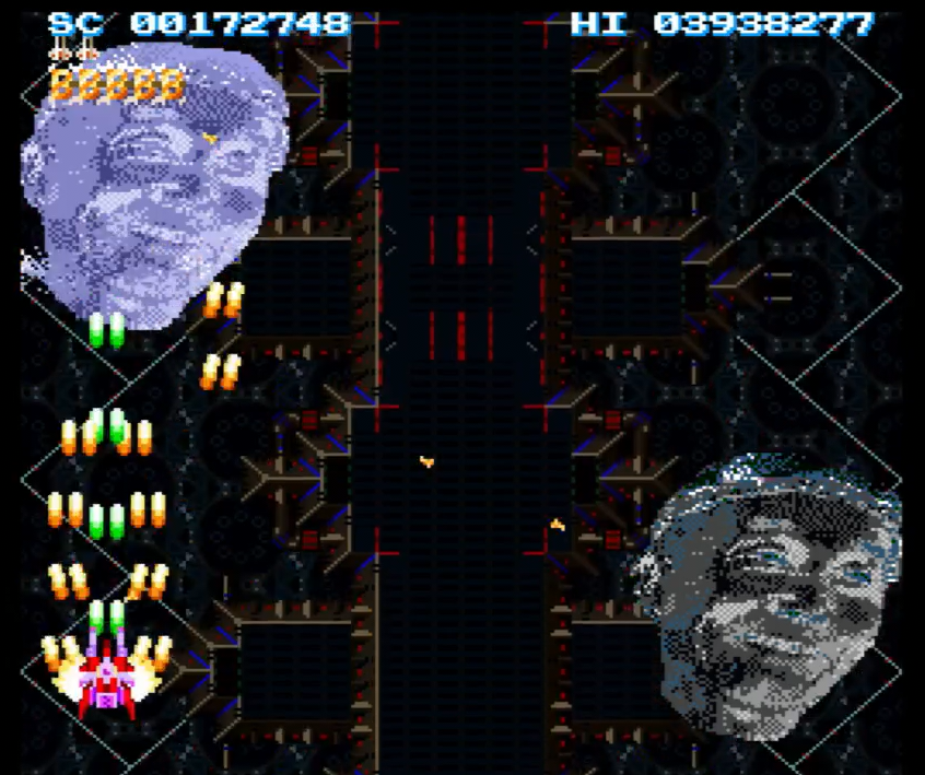
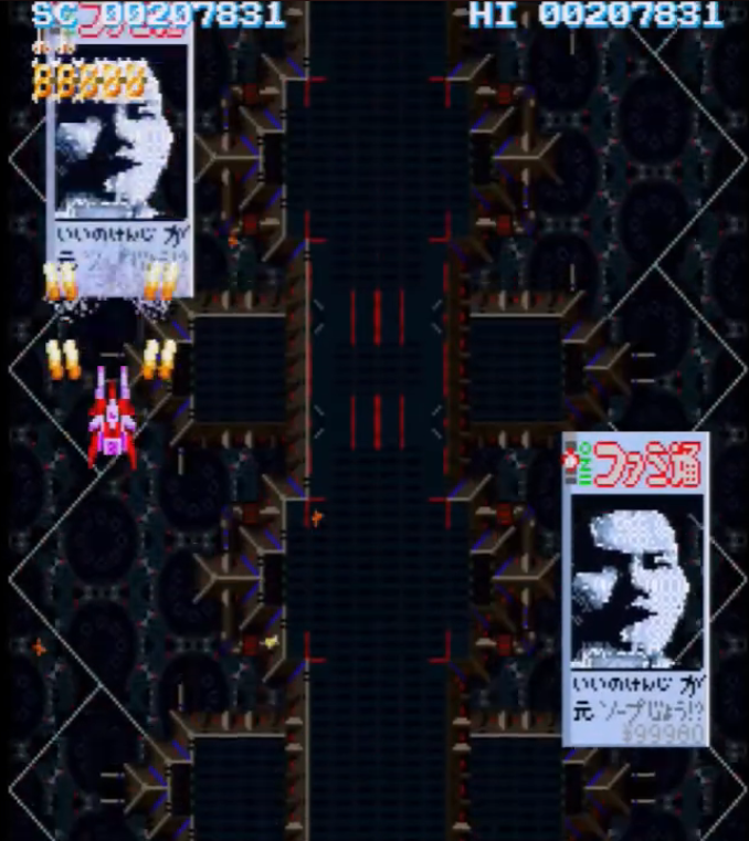
Stage 1 Boss in 0.6Stage 1 Boss in 1.0Stage 2 Boss in 0.6Stage 2 Boss in 1.0Stage 3 Boss in 0.6Stage 3 Boss in 1.0
I am hoping to track down the other versions too at some point, but it’s at least nice to have one preserved dump out for this now 🙂
Gameplay
Here is a quick video of me playing through the first loop of the game.
As you can see in the video, some of the boss sprites are quite different from the release used in other Youtube videos right now.
Installation instructions
Instructions are for original X680x0 hardware. I don’t have much experience using emulators, but I assume it should be similar there.
This version of the game is really made to run with Cho Ren Sha version 0.6 (Comiket 52), but since that version is undumped, and you probably want to play a later version anyways, here’s what I did to get it running with CRS68k v1.01. That version lacks a few of the earlier PCM files, so they need to be grabbed from an earlier version.
It seems to run fine like this (see video above), but it’s possible some stuff is wrong compared to using this with CRS68k v0.6.
Requirements:
X68000 or X68030 with at least 15MHz cpu frequency.
This is apparently to handle the additional PCM, as noted in dev diaries on the floppy.
Copy pcm_dat/shot2.pcm and pcm_dat/fmake0d.pcm from CRS68k v0.45 to pcm_dat/ for the v1.01 install
Copy all Chobi Ren Sha files into the same folder as well
To get the TLB music to work, you need to add the lines at the code-block below this list to BGM_DAT/sz2_bgm.cnf at the top of the ボスBGM section*.
Run チョビるぜ!!.BAT to start. (You may want to rename this to something easier to type)
Enjoy!
*Stuff to add to BGM_DAT/sz2_bgm.cnf:
* True Last Boss
BGM_No.$20 : FILE = BGM_DAT¥るざりん¥SZ2_B3.MDC
I do realize that these instructions are somewhat complicated. Someone else might want to distribute a pre-patched LZH file with the contents of this at some point and/or include this in the SCSI HDD images with games that people tend to use nowadays.
Misc stuff
The only footage I’ve found of people playing this game (the later version):
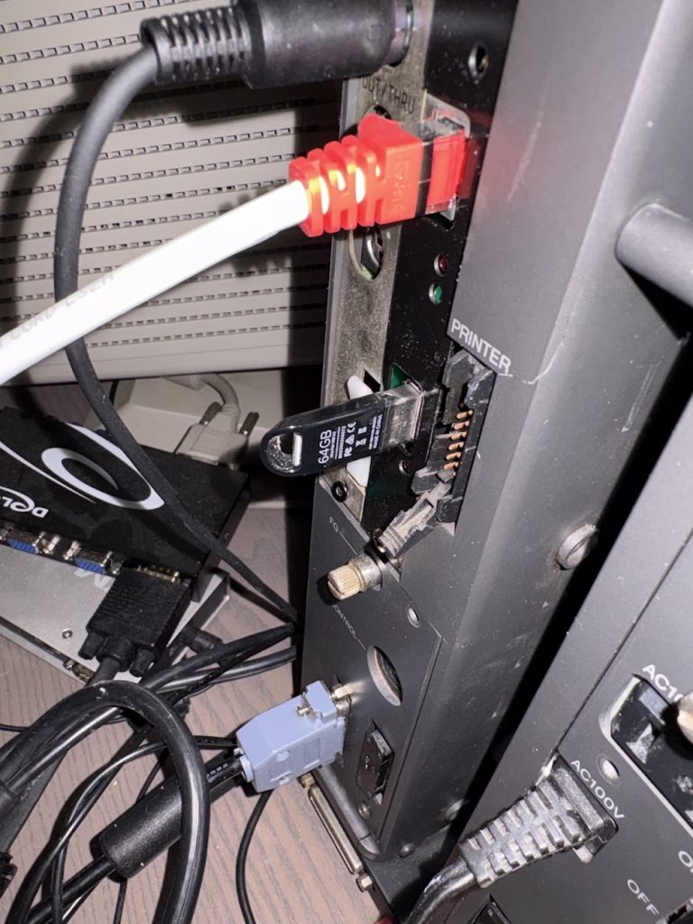
I looked around a bit recently on what’s possible to do with the USB port of Nereid on X68000, and saw that the currently available drivers seem to be:
Mouse
Gamepad
USB Floppy drive
… but I couldn’t find anyone that have written drivers for using USB memory sticks as hard drives.
Have been messing around with this quite a bit now and seems to work really well. Since the drive mounts as FAT16 instead of using binary images like BlueSCSI, it’s now extremely easy to transmit files between my computer and the X68000!
Since this is just something I shat out kindof quickly with a LLM, I can’t say I’m particularily proud of this thing, but it’s a weird new world we live in now when making these things is suddenly easy.
If I were to implement this myself, it would have taken me weeks/months of research to figure out how to approach it. Now I can just prompt some machine in the cloud and it spits out a surprisingly well written device driver for and old machine like this.
I have a X68000 setup at my work desk which I only use for games, and I found it annoying to have to reach for the keyboard every time I wanted to launch a game through LHES.
My initial thinking was that I could create a custom game launcher which supported controllers, or modify LHES to have support for them. After thinking about it a bit, I realized that a better option would be making a utility for mapping joypad inputs as keyboard inputs.
I wasn’t initially sure if this was possible, but after some experimentation, this turned out really well!
As an example, to use LHES as a launcher with the standard SCSI image that people are using (with !Start.bat scripts for launching games), you can run:
Player 1 controller is used for navigating into games (Double tap B to quit LHES and run !Start.bat). Player 2 controller is used to swap between HDD drives.
No changes are needed to AUTOEXEC.BAT/CONFIG.SYS. Just run the util to remap things.
Only tested with LHES, SWITCH and ED so far, but should work for a lot of stuff.
Note that since this relies on hooking things up to the VBLANK interrupt, apps/games which require ownership of this will NOT work.
A while back, I bought a cheap X68000 Compact that didn’t boot, and fixed it up well enough to be able to boot in 10Mhz mode, but not 16Mhz mode.
This involved both fixing issues with RAM accesses + bad logic IC’s related to audio. See earlier post here.
Considering it was bought broken and that repair took a lot of debugging, I was mostly happy with that outcome, but wanted to get back to fixing the 16Mhz mode too.
This summer, I finally went back to it and managed to fix it, so here’s a quick writeup.
Figuring out the crash
I started by probing the address lines of the X68000 until HALT was asserted, and noticed it crashed at the same spot as it did previously in 10Mhz mode before i fixed that mode.
It fails after a read of FF0636 which is a RTS instruction. The return address is incorrect, and things blow up.
Since that was what happened originally in 10Mhz mode, I could just assume that my previous fix was only _mostly_ correct.
Probing the RAM IC’s verified that only two of them were getting CS pulses in 16Mhz mode when LDS and UDS were asserted, while they all were in 10Mhz mode.
Looking back at the earlier “fix”
The previous fix I had for the RAM access was:
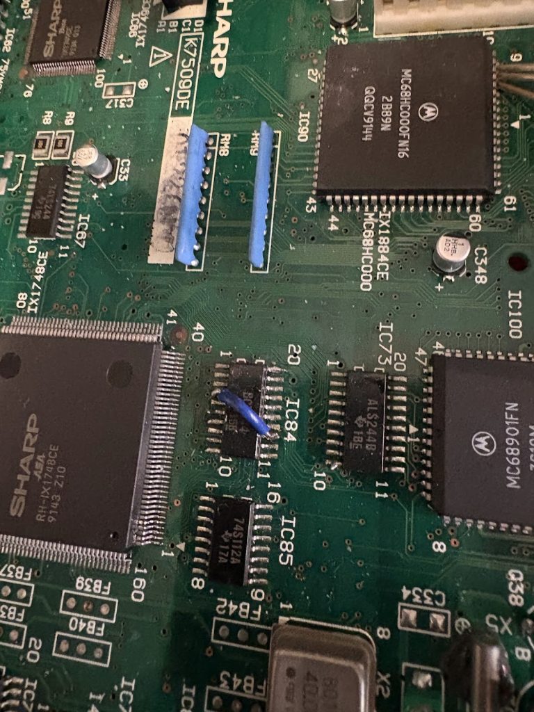
IC84 Pin #13 -> IC84 Pin #4
IC84 Pin #7 -> ASA Pin #3
ASA Pin #3 lifted off pad
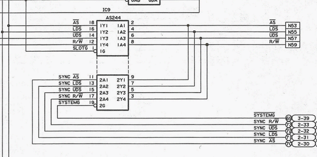
This was inspired by the schematics for the non-compact X68000 XVI (CZ-634C), since the schematics for compact was not available, and it appeared to be wired the same when inspecting signals.
Going back and reverting those fixes and probing things more carefully, I noticed that the compact does NOT have this exact wiring though.
When looking at UDS which were known to work, I can see that Pin#15 and Pin#6 are wired together, and continuity testing shows that this is also wired to the ASA UDS port.
On my machine, I could see that IC84 Pin #13 was NOT connected to Pin #4, which seemed weird, since I’d expect LDS to be have the same as UDS. Trace should be under IC, but assuming trace damage, the previous initial patch was correct.
What was wrong was the IC84 Pin #7 -> ASA Pin #3 part (which should be correct on the non-compact).
Simply reverting that fix, and cleaning up the bodge a bit made the machine boot in 16Mhz mode too.
Happy ending
Very glad to have this fixed. Machine now works 100%. Getting sidetracked a bit by messing up the wiring in the previous repair was awkward, but simply going back and probing things carefully made for a rather quick fix!
The best type of mistakes are ones that can be easily reverted.
For people emulating the games, this should not have any effect really. This is mostly for documenting the behavior of boards, and for people doing stuff such as custom video scalers.
In the earlier post I wrote a little about the CZ-6MO1 Magneto Optical drive I bought for Sharp X68000.
Unfortunately, after some use, it smelled of dead capacitors (fishy and bad), and I was getting inconsistent results with reading disks.
Since this thing is old, I opened it up and did a restoration. This post covers this with some pics, and then a cap-list towards the end.
Opening the device
With the top off, the drive looks like this. The PSU is facing the camera and behind it is the MO assembly sandwiched between two PCBs, with another two sitting behind it near the back fan.
PSU is fairly beefy. 3A on 12V and 3A on 5V.
Popping off top reveals back of one of the “Analog PWB”. TONS of variable resistors, which I guess are used for fine tuning this thing. There’s some flux residue ot something, but nothing here looks very bad.
Popping off the rear part with connectors and fans reveals the rear boards, which are stacked on top of eachother with a connector.
Removing top PCB requires being very careful, since it has a flex table which is kindof short. Moving it like below, and then unclipping the connector worked well.
Top board is kindof dirty, and some caps look iffy.
Now the main MO drive assembly can be removed and flipped upside down. Removing the cover there reveals another PCB
Apparently this is the digital power board. This looks clean and no electrolytic capacitors to worry about.
At this point, things were as much dissassembled as I dared to go. The Drive itself could be opened up further, but I have no experience servicing MO-drives, so I thought it best to leave it as is for now unless I notice issues there.
Power supply opened up easily and the fishy smell was strong there.
Bulging and leaking caps, bad times. Needed some real work.
Recapping
The only restoration I did on this thing as this point was a good cleaning and a full recap of all the boards. This turned out to be sufficient.
The caplist I made is below. Measurements are not exact, but get something close enough and it should be fine. Digikey links are what I used. For some, the voltage rating is upped a bit compared to the board ones.
Interestingly, after recap I got these Fujifilm disks to ALMOST work too, which I had zero success with before recapping. They will initialize fine, but they seem slower and make a lot more noise when reading/writing compared to the Sony ones. After copying some files to it, the system will no longer write more data. Not sure if that’s an issue with my unit or if these are incompatible in some way.
I will just use the Sony EDM-1DA1 ones in the future due to this, since they work great!