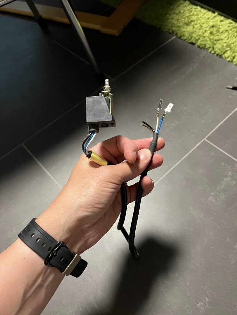
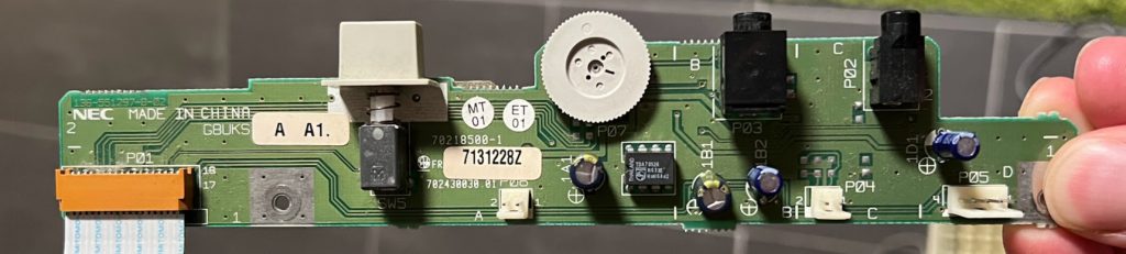
Since I wanted to be able to have a SCSI to Flash adapter connected internally to my device, I had to make some adjustments to the hardware.
Hardware
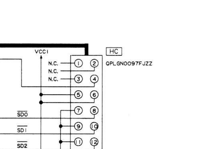
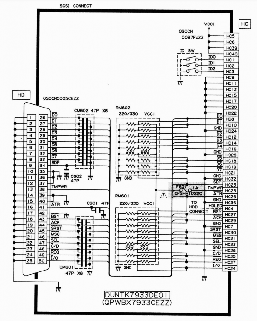
I wanted to hook up an internal SCSI HDD to my X68030, and decided that instead of trying to manufacture a cable for this, I’d just make a quick replacement SCSI IO board with the proper connector. This board has the same configuration of resistors and capacitors as the original board, but lacks the external connector. It has headers for setting the SCSI ID, but it’s fine to leave this unpopulated and just use SCSI ID=0 for the X68030.
SCSI Device setup
Setup is quite minimal.
There shouldn’t really be any settings needed to be changed in SWITCH.X. Leaving device boot as STD works, and either 0 or 7 as SCSI_ID works fine.
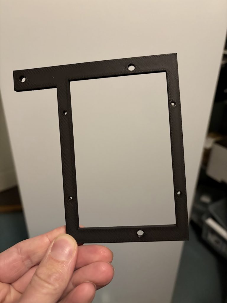
I had a spare Henkan Banchou 変換番長 Pro from a previous project that I decided to use. I designed and 3D printed a bracket (STL is at end of this post) for this to fit in the top right of the X68030, since that’s where the internal HDD is in CZ-510C.
I loaded this with the SxSI-SCSI HDD Image v3.01 from NFG Games forum, and things pretty much just worked right away, once I connected the cable.
Power is supplied using the flat cable (as long as the connected device doesn’t require more than 1A).
I finally got SCSI working on my X68030 CZ-500C, so thought I’d do a writeup on what I learned. It will be in two parts, where the first one covers the default CZ-500C SCSI support, and the second part covers a new adapter I made for using internal SCSI devices.
CZ-500C SCSI Internals
X68030 has proper SCSI support, not just SASI as some of the earlier X68000 models. CZ-500C does however lack cabling for internal SCSI HDD (which CZ-510C has). The internal connector used from the main board to the SCSI IO board is a non-standard 40-pin flat cable. The schematic for CZ-500C including the SCSI board can be found here.
The IO board itself is quite simple. Other than the connectors and ID switch, it just has a terminating 33oΩ/220Ω resistor network, a bunch of capacitors and a 1A fuse for the external power delivery. It is mounted on top of another IO board for the external floppy, and easy to remove with two screws.
If the SCSI board is not connected to the bottom PCB of the X68030, the system will not start.
External connectors
The external SCSI connector is a “Micro Centronics” connector, which is hard to find proper cabling for. It seems like the Japanese term for these are アンフェノールハーフ50 (Amphenol half 50) or アンフェノールハーフピッチ50 (Amphenol half pitch 50).
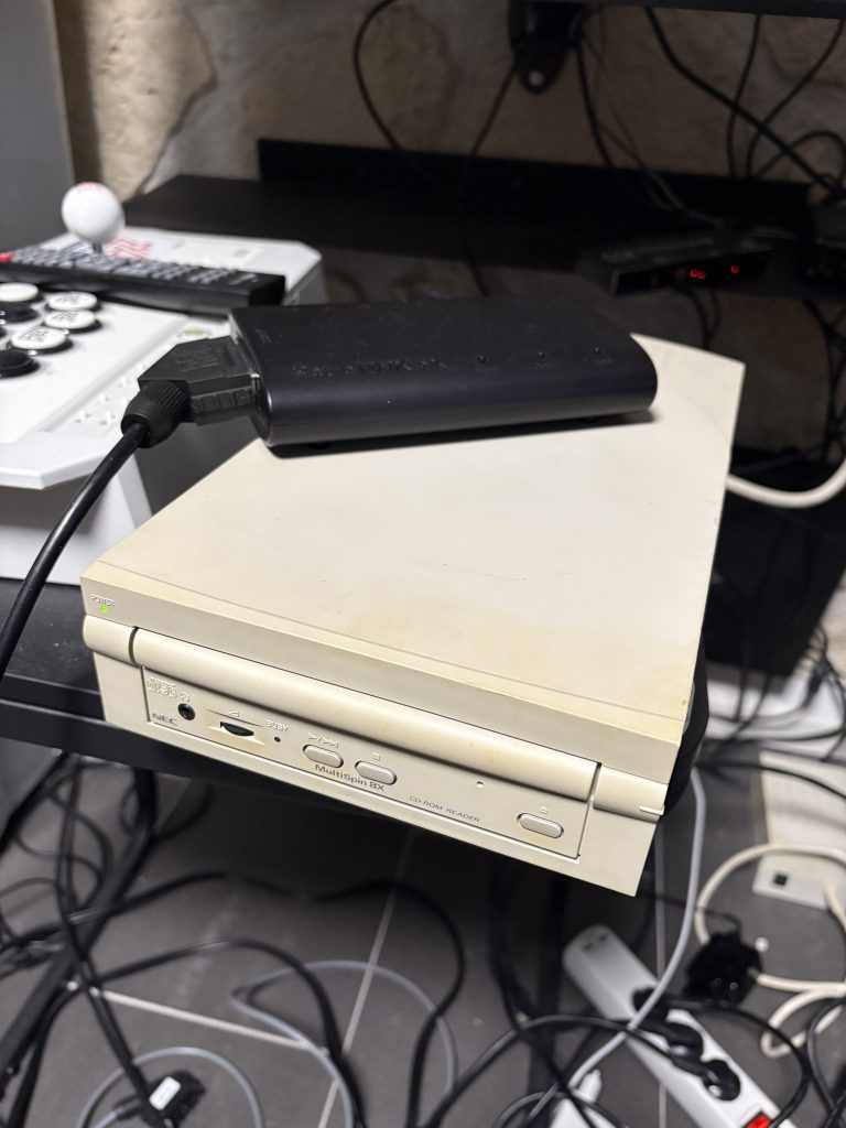
When looking for adapters to full-size Centronics, you can search for that in combination with アンフェノールフル 50 (Amphenol full 50), and look for a cable with a male Micro connector that goes to a female full size connector. This can then be hooked up to a Centronics Bluescsi device. Example from an Mercari auction:
There is a SCSI ID switch on the back of the unit. This doesn’t seem to be related to the external device, but rather the SCSI ID that the X68030 uses. Weirdly there’s also an option for this in SWITCH.X so I’m not really sure which option has priority. The compact version of X68030 does not have this switch, nor does other X68000 models as far as I can tell.
Did a quick recap of my new PC-9801-86, and thought I’d add some notes to simplify for other people. There’s an earlier Japanese caplist here that I used as a base, but they used THT caps for the recap which I didn’t want to do.
Note that C33 and C34 are bipolar caps. The mouser links below link to the proper ones, but in my actual recap I just used polarized capacitors which seems to work as well (the Japanese link above did this too). It should be better to use bipolar caps though, so I might swap them later.
This is honestly the only tricky part, and the main thing is that the disk images are incompatible with greaseweazle as far as I can tell, so first you need to open Virtual Floppy Image Converter and convert it to a FM Towns compatible format.
Select “D88 format” as format and click the open icon to the left
Select FDMINI.BIN
This will then spit out a D88 image.
Connect your Greaseweazle over USB. Hook up the 3.5″ floppy drive to it. Use a twisted floppy cable. Run:
gw write fdimage.d88 --drive=A
This will produce the floppy you need
Booting
Connect the SCSI CD-ROM drive to the SCSI port at the back of the FM Towns and put a CD in it. Use the boot floppy and it will automatically boot from the external CD-ROM.
… which is really nice, because I own most of the early Psikyo games, but on this hardware I only had the original PCBs for Strikers II, Gunbird 2 and G-Taste (best jong game).
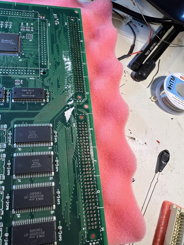
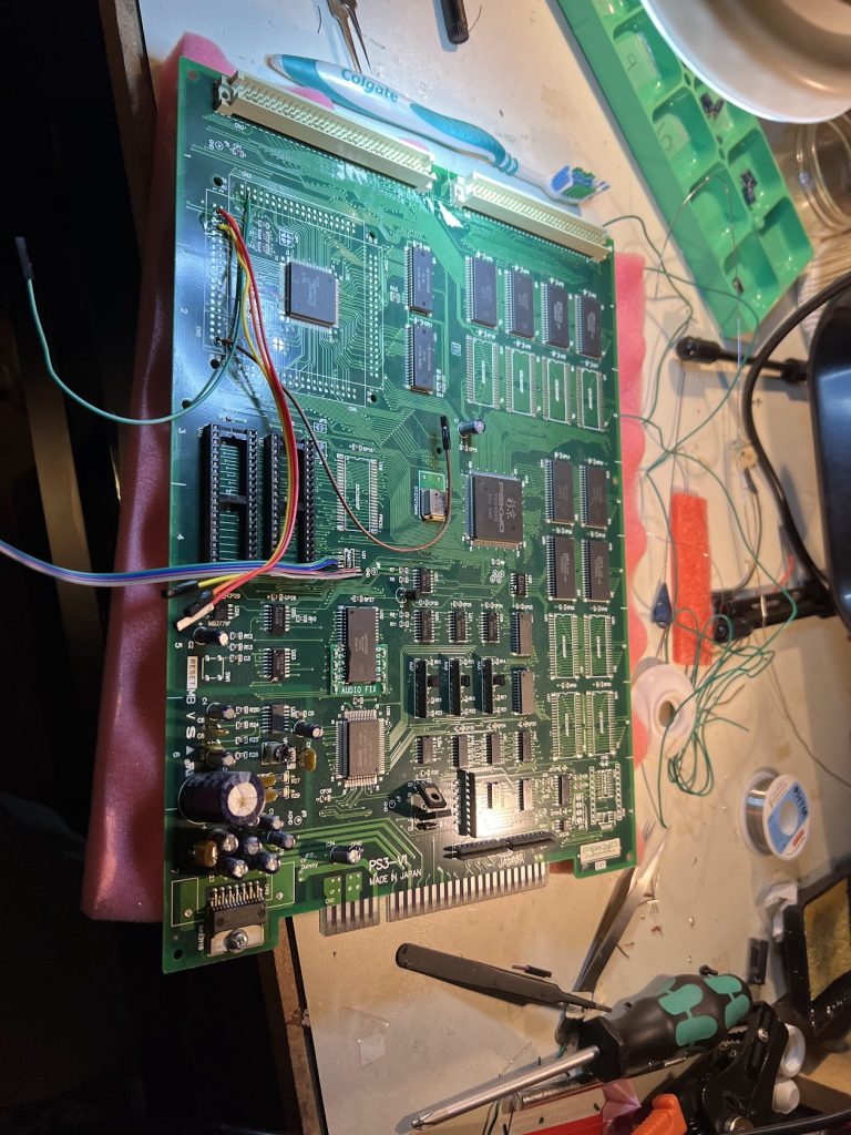
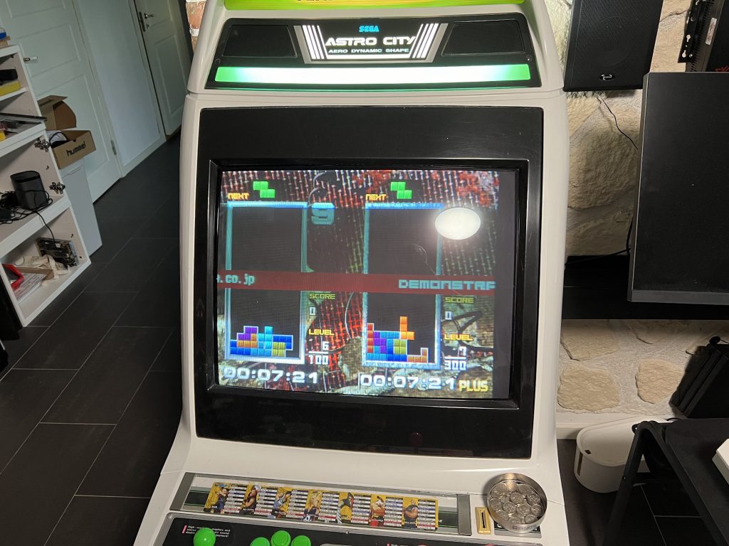
Went ahead and converted my Strikers II which was… not too bad! Clearing the holes for the adapters of the sub-pcb was a bit of work, but with a good desoldering station it was fine.
With an inspection microscope, the rest of the install was pretty simple.
The PSU is the same size as standard “small” ATX power supplies, which is 150mm (W) x 86mm (H) x 140mm(D). For the replacement PSU, make sure to find something with suitable power placement to fit the holes in the case. Modern PSU’s will usually have different fan placement, so you might have to track down some older ones.
The V13 uses standard AT for the main two connectors except:
-5V is not populated
PG (power god) is not populated
This means that the cabling is as follows:
Black = GND
Green = 3.3V
Red = 5V
Yellow = 12V
Blue = -12V
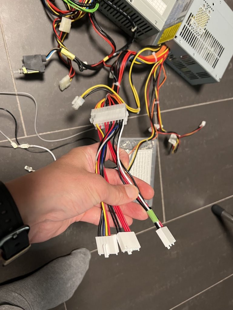
I simply grabbed two AT->ATX power adapters and moved one of the AT cablings to free slots for 3.3V and GND in the ATX adapter. One GND pin is unpopulated, but that should be fine (and does seem to work well).
The (probably nicer) alternative is to simply remove the cabling from the original AT power supply and crimp ATX pins on those, to get the colors completely right too.
For power, rip out the original AT powr wiring and hook up the blue and white wires to PS_ON and GND on ATX. This will make the PSU work similar to the original one.
Did a full recap on my V13 PC-9821. Here is the cap list. I did double check the values, but there’s still a possibility for errors, so I recommend checking them yourself too.
Motherboard
1A2: 100u, 16v (6.5mm)
1A9: 100u, 16v (6.5mm)
1A10: 47u, 16v (5mm)
1B13: 10u, 16v (5mm)
1H1: 10u, 16v (5mm)
1H2: 10u, 16v (5mm)
1H3: 47u, 16v (5mm)
1H4: 10u, 16v (5mm)
1H5: 10u, 16v (5mm)
1J3: 47u, 16v (5mm)
1J5: 47u, 16v (5mm)
1J6: 10u, 16v (5mm)
2B5: 47u, 16v (5mm)
2E1: 47u, 16v (5mm)
2H7: 47u, 16v (5mm)
2K3: 47u, 16v (5mm)
3C5: 47u, 16v (5mm)
3D1: 47u, 16v (5mm)
3E11: 10u, 16v (5mm)
3E12: 10u, 16v (5mm)
5B1: 3300u, 10v (12.5mm)
5B2: 47u, 16v (5mm)
5C2: 47u, 16v (5mm)
5M6: 47u, 16v (5mm)
6F3: 10u, 16v (5mm)
6N7: 10u, 16v (5mm)
7F8: 10u, 16v (5mm)
7J7: 10u, 16v (5mm)
7K6: 10u, 16v (5mm)
8G1: 47u, 16v (5mm)
8J1: 10u, 16v (5mm)
9D2: 47u, 16v (5mm)
9D3: 10u, 16v (5mm)
9E3: 10u, 16v (5mm)
9F9: 10u, 16v (5mm)
9G1: 10u, 16v (5mm)
10B2: 47u, 16v (5mm)
10D2: 47u, 16v (5mm)
10F1: 47u, 16v (5mm)
10G1: 10u, 16v (5mm)
10K1: 10u, 16v (5mm)
Front IO Board
1A1: 100U, 16V (6.5mm)
1B1: 100U, 16V (6.5mm)
1B2: 10u, 16V (5mm)
1D1: 10u, 16V (5mm)
CBUS Riser
C1: 10u, 16V (5mm)
C2, C3: Unpopulated
C4: 47u, 16V (5mm)
C5: 10u, 16V (5mm)
C6: 10u, 16V (5mm)
C7: 10u, 16V (5mm)
C8: 47u, 16V (5mm)
The slots are 100 Pin 2×50 Edge connectors. 5mm between pin rows. Pin rows have 2.54mm spacing
Sound board
Component markings are super confusing here, but it has
My X68000 (CZ-600C) was failing VRAM checks for Text RAM, and there wasn’t much info available about that online, so I’m writing some up here.
TL;DR information that is good to know:
On CZ-600C, IC1-IC16 is Text VRAM. IC17-IC32 is Graphics VRAM. All 32 of these RAM chips are on the Graphics sub-board.
The RAM IC’s used are MB81461-12 (32 of them).
Addressing for these can be found on the X68000 schematic. This will help narrow down which one is faulty, if you know the bad adresses.
Donor RAM IC’s can be found in Mega Drive units (two per unit).
Debugging the issue
Running MEMTEST (philly 1993) showed this error for TEXT MEMORY.
For more indepth understanding of the errors I ran Memtest68k which showed the range 00e725c – 00e725fc being bad, with Bits in Error Mask: 0000f000.
Looking at the technical guide for X68000 available here , this means that the error is in the last page of Text RAM, and the problematic bits are the highest 4 adresses. Looking at the schematic available on that page, this looked to be either IC16 or IC32 (turns out later it was IC16).
Addressing for Text and Graphics VRAM is slightly different, but the lower numbered IC’s map to the lower address ranges (as expected), and the data bus numbers for the pins in the schematic can help narrow down where the issues is.
To verify if it was IC16, I desoldered pin1 and pin2 on it, and wiggled them a bit while running memory checking. This produced more errors in the page of the already faulty range, which verified that it was indeed this IC that had issues. The main reason for doing this verification was that I was not sure if the first or last 16 RAM chips were for the Text part of VRAM.
After this, I was sure which part was bad.
Fixing the issue
Fixing the issue at this point was pretty straight forward, since it just meant swapping the bad part. Sourcing these are a bit awkward, but there are some available at aliexpress. I didn’t feel like waiting though, so I opened up my Mega Drive and grabbed the video RAM from that, since it uses the same IC’s. I’ll replace that later with the aliexpress ones, whenever they show up.
For desoldering these, you NEED a proper desoldering station/gun. I use a HAKKO FR301-22, but you can use cheaper ones as well. Overall, extracting this type of package is more annoying that DIP packages, but it worked out fine, with not messed up pads.
Removing RAM from Mega Drive
Next step is removing graphics sub-board and RAM chip from the X68000. Then just solder the Mega Drive RAM in the place of the bad RAM.
And there we go, memory test works now! All is good.