Did a quick recap of my new PC-9801-86, and thought I’d add some notes to simplify for other people. There’s an earlier Japanese caplist here that I used as a base, but they used THT caps for the recap which I didn’t want to do.
Note that C33 and C34 are bipolar caps. The mouser links below link to the proper ones, but in my actual recap I just used polarized capacitors which seems to work as well (the Japanese link above did this too). It should be better to use bipolar caps though, so I might swap them later.
The PSU is the same size as standard “small” ATX power supplies, which is 150mm (W) x 86mm (H) x 140mm(D). For the replacement PSU, make sure to find something with suitable power placement to fit the holes in the case. Modern PSU’s will usually have different fan placement, so you might have to track down some older ones.
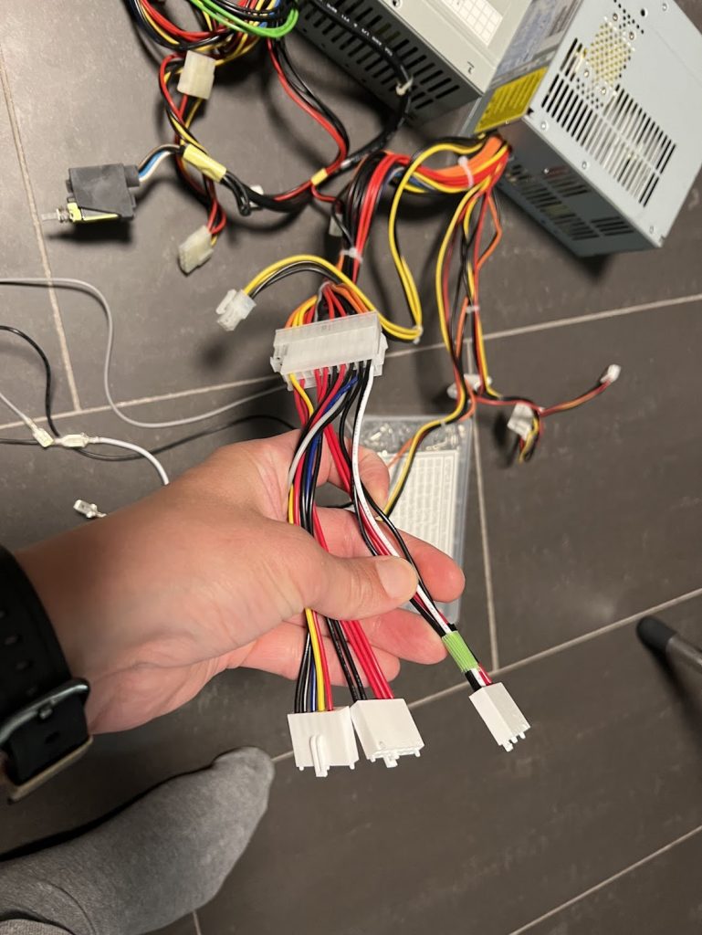
The V13 uses standard AT for the main two connectors except:
-5V is not populated
PG (power god) is not populated
This means that the cabling is as follows:
Black = GND
Green = 3.3V
Red = 5V
Yellow = 12V
Blue = -12V
I simply grabbed two AT->ATX power adapters and moved one of the AT cablings to free slots for 3.3V and GND in the ATX adapter. One GND pin is unpopulated, but that should be fine (and does seem to work well).
The (probably nicer) alternative is to simply remove the cabling from the original AT power supply and crimp ATX pins on those, to get the colors completely right too.
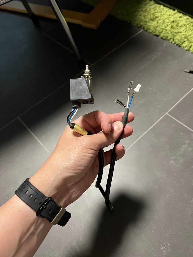
For power, rip out the original AT powr wiring and hook up the blue and white wires to PS_ON and GND on ATX. This will make the PSU work similar to the original one.
Did a full recap on my V13 PC-9821. Here is the cap list. I did double check the values, but there’s still a possibility for errors, so I recommend checking them yourself too.
Motherboard
1A2: 100u, 16v (6.5mm)
1A9: 100u, 16v (6.5mm)
1A10: 47u, 16v (5mm)
1B13: 10u, 16v (5mm)
1H1: 10u, 16v (5mm)
1H2: 10u, 16v (5mm)
1H3: 47u, 16v (5mm)
1H4: 10u, 16v (5mm)
1H5: 10u, 16v (5mm)
1J3: 47u, 16v (5mm)
1J5: 47u, 16v (5mm)
1J6: 10u, 16v (5mm)
2B5: 47u, 16v (5mm)
2E1: 47u, 16v (5mm)
2H7: 47u, 16v (5mm)
2K3: 47u, 16v (5mm)
3C5: 47u, 16v (5mm)
3D1: 47u, 16v (5mm)
3E11: 10u, 16v (5mm)
3E12: 10u, 16v (5mm)
5B1: 3300u, 10v (12.5mm)
5B2: 47u, 16v (5mm)
5C2: 47u, 16v (5mm)
5M6: 47u, 16v (5mm)
6F3: 10u, 16v (5mm)
6N7: 10u, 16v (5mm)
7F8: 10u, 16v (5mm)
7J7: 10u, 16v (5mm)
7K6: 10u, 16v (5mm)
8G1: 47u, 16v (5mm)
8J1: 10u, 16v (5mm)
9D2: 47u, 16v (5mm)
9D3: 10u, 16v (5mm)
9E3: 10u, 16v (5mm)
9F9: 10u, 16v (5mm)
9G1: 10u, 16v (5mm)
10B2: 47u, 16v (5mm)
10D2: 47u, 16v (5mm)
10F1: 47u, 16v (5mm)
10G1: 10u, 16v (5mm)
10K1: 10u, 16v (5mm)
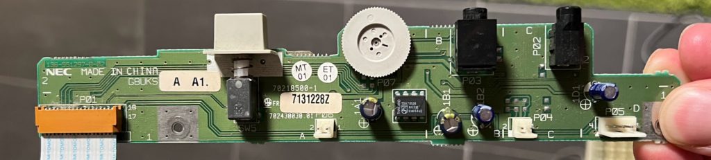
Front IO Board
1A1: 100U, 16V (6.5mm)
1B1: 100U, 16V (6.5mm)
1B2: 10u, 16V (5mm)
1D1: 10u, 16V (5mm)
CBUS Riser
C1: 10u, 16V (5mm)
C2, C3: Unpopulated
C4: 47u, 16V (5mm)
C5: 10u, 16V (5mm)
C6: 10u, 16V (5mm)
C7: 10u, 16V (5mm)
C8: 47u, 16V (5mm)
The slots are 100 Pin 2×50 Edge connectors. 5mm between pin rows. Pin rows have 2.54mm spacing
Sound board
Component markings are super confusing here, but it has