

A month or so ago, someone was selling a broken JVC DT-V1710CG for quite cheap an hour or so from here by car. These are quite exceptional pro monitors that work with everything from 15khz up to 720p/1080i high definition signal. They also handle 24khz from old Japanese computers very well.
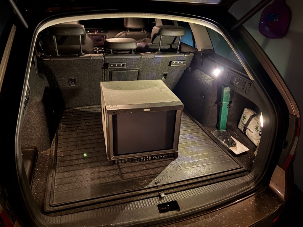
I already own one of these, but would like to own another one, and my thinking was that having a working one as reference should help with repair (it did).
When connecting it up, it was indeed quite broken. Colors are completely messed up, and the beam wasn’t firing at all times leaving empty gaps in what was being drawn. Sync appeared fine though since picture was otherwise stable.

I started by dissasembling the entire thing to have a look at the internals for obvious things that could be busted. Overall, the condition of the internals wasn’t too bad. I had never dared dissasemble the existing one I owned, so it was also nice to learn how to do that.

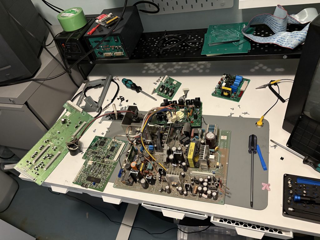
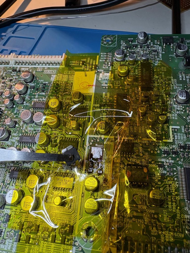
Something I noticed pretty quickly when taking it apart was that there was a burnt looking spot around a voltage regulator on the signal board of the machine. I made a note about this, and put the monitor back together again. Once mostly reassembled, I tried swapping signal board with my working monitor, and it became clear that this was the problematic board of the monitor, since image was fine once swapped (and the known working monitor started displaying same issues).

I desoldered the regulator and tested it on my bench, and it did indeed seem to be busted, pushing out higher voltage than it should. Swapping it out for another one did however not fix the issue with the image.
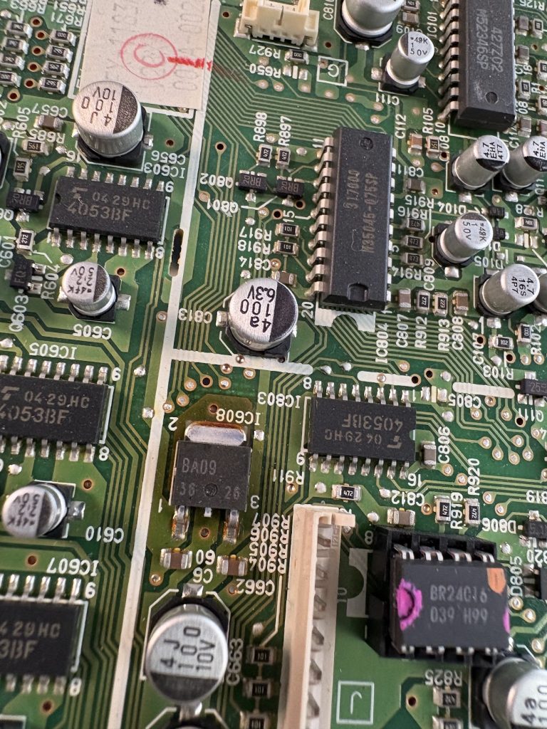
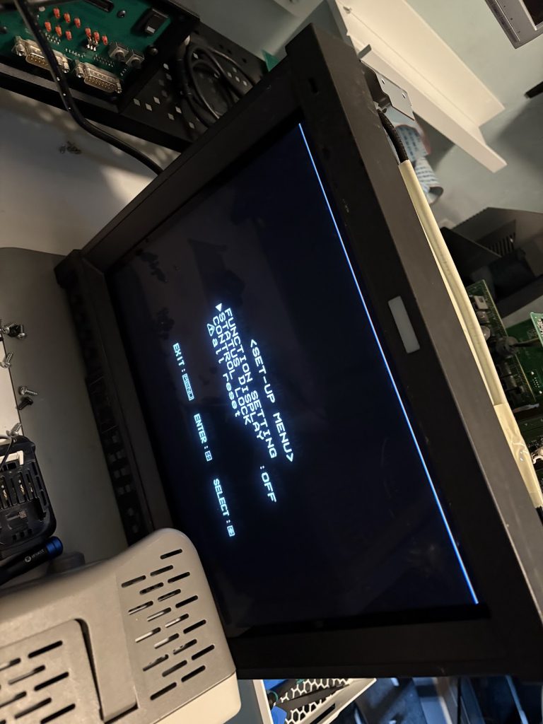
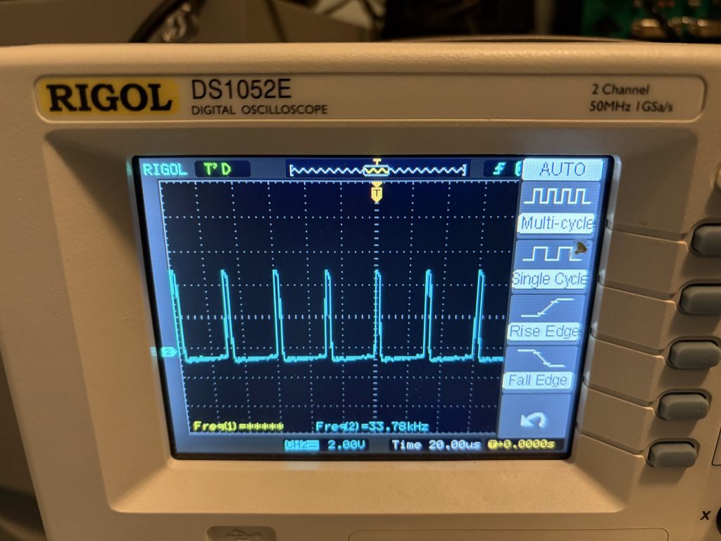
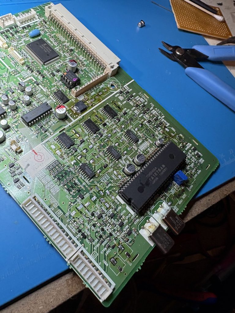
Scoping the HSync and VSync of the neck board showed that sync signals were indeed fine, and since the microcontroller seemed to function well with the menus, I assumed the problem would be somewhere on the area of the board housing the TA1276AN RGB processor.
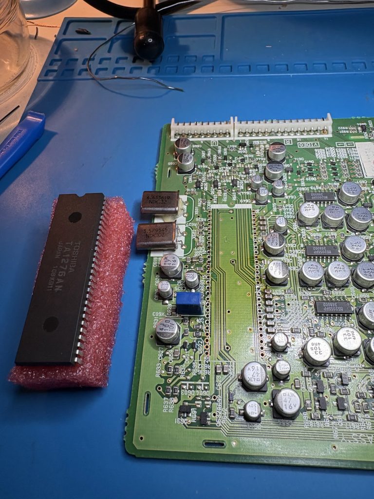
I initially thought that the RGB processor would be the faulty part, since the image was overall messed up and not just a single color being faulty, so I desoldered it, mounted a socket for a new one and sourced one on Ebay. This turned out to do nothing, so that was some wasted money and effort.
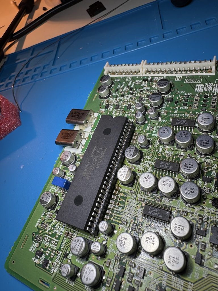
At this point, I wasn’t really sure which part was messed up so I scoped around a bit and noticed the crystals near the processors did not show stable oscillations. I decided to swap them and most easily accessible capacitors. In retrospect, it’s unlikely the crystals were at fault, but it was a cheap and quick swap so why not. I left some capacitors near the socket, since replacing those is very awkward (mistake).
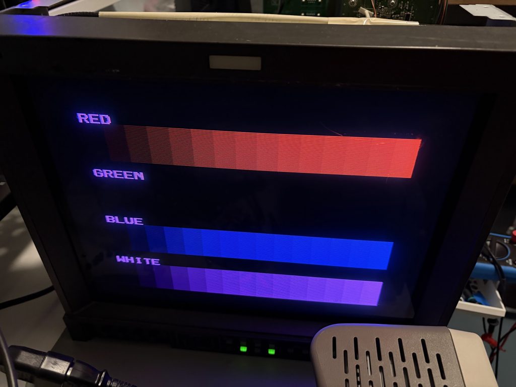
This recap made major progress. Image was now looking great… but lacked green. Scoping showed the green output being sortof present, but looking very different and lower in signal compared to green and blue.
After getting sidetracked a bit looking for bad transistors, I realized that one of the capacitors I had not swapped was connected to “G S/H” on the RGB processor. Swapping that capacitor to a new one fixed the issue, so that one was definitely messed up. Likely at least one other significant one was as well which caused the other issue.
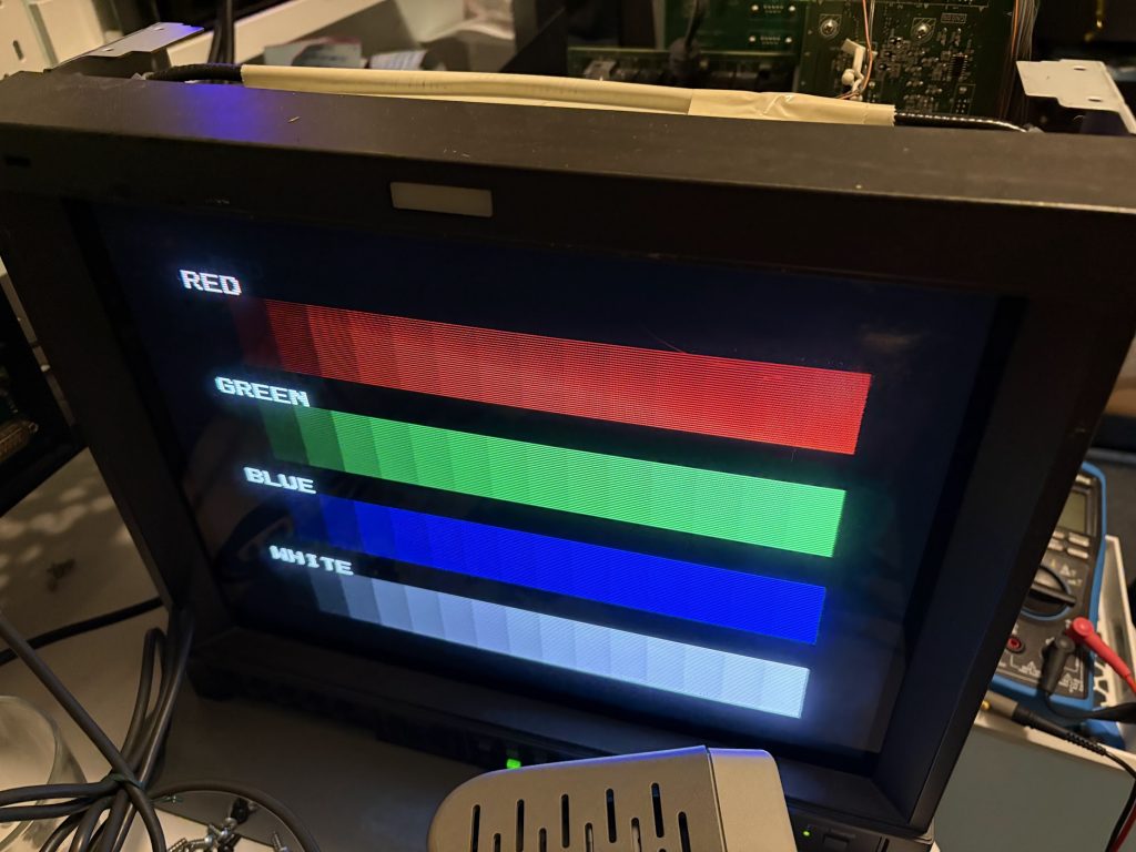
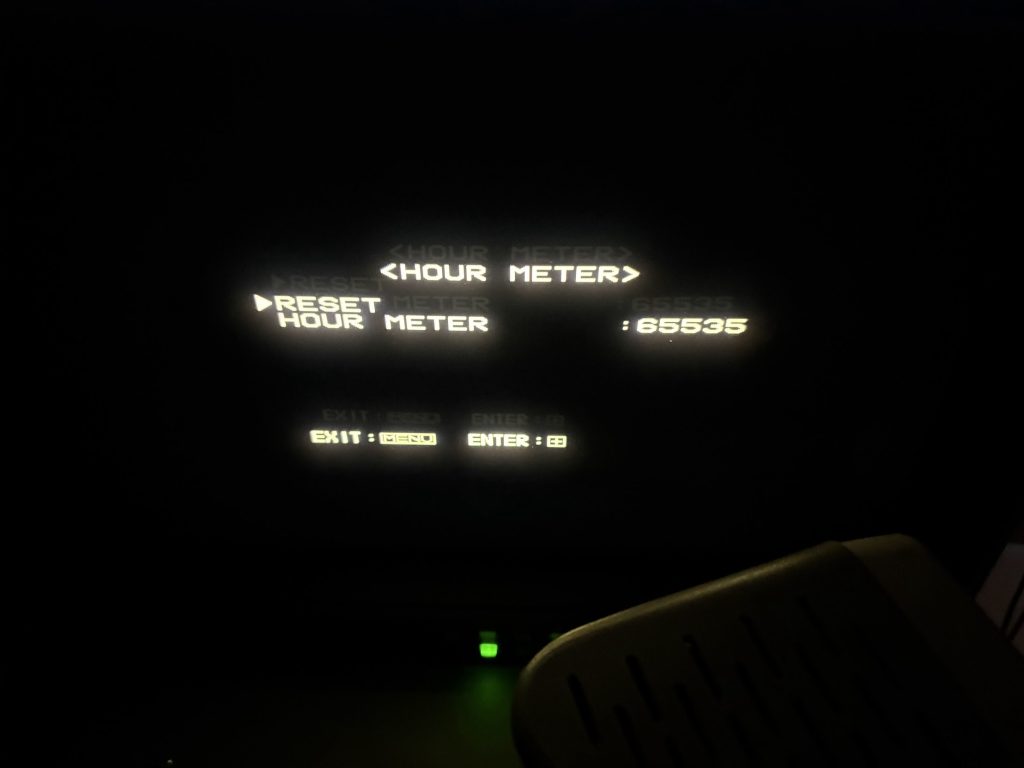
With it swapped, image is now very solid! Looks like this monitor has lived a hard life, since the hour count in service menu is maxed out 🙂
I’m not very experienced working on CRT’s, so this was a fun project, and now I have a very nice monitor for my test bench!